Arduino Fake Bomb
prusaprinters
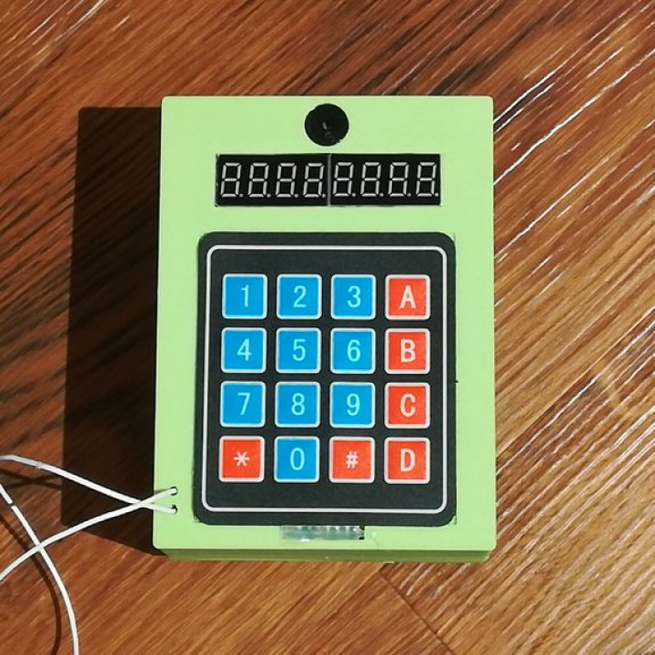
<p>Hello reader,</p><p>this is my little fake bomb for adventure games or for fun. I actually designed this for a boy's scout game but I thought maybe this fake bomb would be helpful to some people, for instance for birthday parties or only plain building fun.</p><h3>Watch the Video!!!</h3><figure class="media"><oembed url="https://www.youtube.com/embed/K47BuDPVzD0?feature=oembed&autoplay=1"></oembed></figure><p><strong>Watch this video because it's cool.</strong></p><h3>Parts</h3><p><img src="https://content.instructables.com/ORIG/FX7/Q35I/JSPAAHIC/FX7Q35IJSPAAHIC.jpg?auto=webp&frame=1&width=929&height=1024&fit=bounds&md=5aeeb4ce6fb7572dccbdcf05d07dcc4a" alt="Parts"><a href="https://content.instructables.com/ORIG/FX7/Q35I/JSPAAHIC/FX7Q35IJSPAAHIC.jpg?auto=webp&frame=1&width=1024&height=1024&fit=bounds&md=5aeeb4ce6fb7572dccbdcf05d07dcc4a"> </a></p><p>What you need:</p><ul><li><a href="https://www.amazon.de/Elektrischer-Silikon-Draht-verschiedene-Isolierter-Temperaturbest%C3%A4ndigkeit/dp/B07G712KWJ/ref=sr_1_4?ie=UTF8&qid=1552932768&sr=8-4&keywords=cables">Cables</a></li><li><a href="https://www.amazon.de/gp/product/B00TK0RIYW/ref=ppx_yo_dt_b_asin_title_o01_s00?ie=UTF8&psc=1">Battery box</a></li><li><a href="https://www.amazon.de/gp/product/B00QLOSFDS/ref=ppx_yo_dt_b_asin_title_o01_s00?ie=UTF8&psc=1">Arduino Nano</a></li><li><a href="https://www.amazon.de/gp/product/B01I37J3D6/ref=ppx_yo_dt_b_asin_title_o06_s00?ie=UTF8&psc=1">Touchpad</a></li><li><a href="https://www.amazon.de/gp/product/B00W8YEG8S/ref=ppx_yo_dt_b_asin_title_o03_s00?ie=UTF8&psc=1">Little buzzer</a></li><li><a href="https://www.amazon.de/CCLIFE-St%C3%BCck-Neodym-Magnete-10x2mm/dp/B0771K32TM/ref=pd_sbs_201_7?_encoding=UTF8&pd_rd_i=B0771K32TM&pd_rd_r=dfba2633-49a9-11e9-8f8f-e50846de54ad&pd_rd_w=IowDA&pd_rd_wg=9Rl8p&pf_rd_p=74d946ea-18de-4443-bed6-d8837f922070&pf_rd_r=PNFERFB1P29VZP2BN3AG&psc=1&refRID=PNFERFB1P29VZP2BN3AG">2 magnets</a></li><li><a href="https://www.amazon.de/gp/product/B00YMIKPCO/ref=ppx_yo_dt_b_asin_title_o01_s00?ie=UTF8&psc=1">7 segment display</a></li><li><a href="https://www.amazon.de/Creality-3D-Drucker-Printer-Economic/dp/B07D218NX3/ref=sr_1_1_sspa?s=ce-de&ie=UTF8&qid=1552933012&sr=1-1-spons&keywords=ender+3&psc=1">3D printer</a></li><li><a href="https://www.amazon.de/Lochrasterplatte-CU-Auflage-einseitig-L%C3%B6tpunkte-160x100mm/dp/B00MOG2JL6/ref=sr_1_9?s=ce-de&ie=UTF8&qid=1549205846&sr=1-9&keywords=lochrasterplatte">Perfboard</a></li></ul><p><strong>3D print</strong></p><p>You should print these parts with an infill over 15%. (*Number of times you need to print each part). You also print these files from:</p><p>MyMiniFactory: <a href="https://www.myminifactory.com/object/3d-print-90713">https://www.myminifactory.com/object/3d-print-9071...</a></p><p>Thingiverse: <a href="https://www.thingiverse.com/thing:3501200">https://www.thingiverse.com/thing:3501200</a></p><ul><li>Backside(1*)</li><li>Batteriecover(1*)</li><li>Frontcover(1*)</li></ul><h3> </h3><h3>Solder the Arduino to the PCB</h3><h3><img src="https://content.instructables.com/ORIG/F3G/4OK4/JTEMUYEA/F3G4OK4JTEMUYEA.jpg?auto=webp&frame=1&fit=bounds&md=9b6c29686cd9c57293e6cb52c6bfbd8c" alt="Solder the Arduino to the PCB"><a href="https://content.instructables.com/ORIG/F3G/4OK4/JTEMUYEA/F3G4OK4JTEMUYEA.jpg?auto=webp&frame=1&fit=bounds&md=9b6c29686cd9c57293e6cb52c6bfbd8c"> </a></h3><p>Solder the arduino to the PCB. Before you solder the arduino to the PCB, think about the right soldering place. (Do you have enough space for all cables?) The right size is 35 mm to 50 mm.</p><h3>Header Pins</h3><p><img src="https://content.instructables.com/ORIG/FI8/Y5QP/JTEMVBPU/FI8Y5QPJTEMVBPU.jpg?auto=webp&frame=1&fit=bounds&md=ae6e7d59f66fe57a4925043374042bcf" alt="Header Pins"><a href="https://content.instructables.com/ORIG/FI8/Y5QP/JTEMVBPU/FI8Y5QPJTEMVBPU.jpg?auto=webp&frame=1&fit=bounds&md=ae6e7d59f66fe57a4925043374042bcf"> </a></p><p><img src="https://content.instructables.com/ORIG/F9N/X1QS/JTEMVI5G/F9NX1QSJTEMVI5G.png?auto=webp&frame=1&crop=3:2&width=720&height=1024&fit=bounds&md=1d75f04e4fe859fc4c15f57ae7517bd6" alt="Header Pins">Solder the 8 header pins from D2 to D9.</p><h3>Battery Box</h3><h3><img src="https://content.instructables.com/ORIG/F4S/3LSR/JTEMVCA3/F4S3LSRJTEMVCA3.jpg?auto=webp&frame=1&width=480&height=1024&fit=bounds&md=8a300301316ad3644b9b4fae6c51f052" alt="Battery Box"><a href="https://content.instructables.com/ORIG/F4S/3LSR/JTEMVCA3/F4S3LSRJTEMVCA3.jpg?auto=webp&frame=1&width=1024&height=1024&fit=bounds&md=8a300301316ad3644b9b4fae6c51f052"> </a></h3><p><img src="https://content.instructables.com/ORIG/FUF/7YW1/JTEMVJHM/FUF7YW1JTEMVJHM.png?auto=webp&frame=1&crop=3:2&width=720&height=1024&fit=bounds&md=8cda1b476773662a29a06841e97e643f" alt="Battery Box">Skin the cables of the battery-box and solder them to the PCB.</p><p>Red = VIN</p><p>Black = GND</p><p>Step 6: Buzzer</p><p><img src="https://content.instructables.com/ORIG/FHI/GM7E/JTEMVKY7/FHIGM7EJTEMVKY7.jpg?auto=webp&frame=1&width=480&height=1024&fit=bounds&md=f81f28256d4eb40559ba39da84bc6951" alt="Buzzer"><a href="https://content.instructables.com/ORIG/FHI/GM7E/JTEMVKY7/FHIGM7EJTEMVKY7.jpg?auto=webp&frame=1&width=1024&height=1024&fit=bounds&md=f81f28256d4eb40559ba39da84bc6951"> </a></p><p><img src="https://content.instructables.com/ORIG/FCA/VEM1/JTEMVJJM/FCAVEM1JTEMVJJM.png?auto=webp&frame=1&crop=3:2&width=720&height=1024&fit=bounds&md=824fd1f48ffa4c2bae2f822a17cfb64e" alt="Buzzer">Cut two cables for the buzzer and prepare all sides for soldering. Then fix the buzzer with some tape because it is easier that way. On the buzzer is a little plus-sign (+) at the top for one side.</p><p>+ = D13</p><p>the side with nothing = GND</p><h3>7 Segment Display</h3><h3><img src="https://content.instructables.com/ORIG/FV1/LIGM/JTEMUYHM/FV1LIGMJTEMUYHM.jpg?auto=webp&frame=1&crop=3:2&width=857&height=1024&fit=bounds&md=114445b918b47c78eda04bd4913b565e" alt="7 Segment Display"><a href="https://content.instructables.com/ORIG/FV1/LIGM/JTEMUYHM/FV1LIGMJTEMUYHM.jpg?auto=webp&frame=1&width=1024&height=1024&fit=bounds&md=114445b918b47c78eda04bd4913b565e"> </a></h3><p><img src="https://content.instructables.com/ORIG/FUJ/PN2L/JTEMVJKD/FUJPN2LJTEMVJKD.png?auto=webp&frame=1&crop=3:2&width=343&fit=bounds&md=c785be44d14402a35948b361cdd5656a" alt="7 Segment Display"><a href="https://content.instructables.com/ORIG/FUJ/PN2L/JTEMVJKD/FUJPN2LJTEMVJKD.png?auto=webp&frame=1&width=1024&fit=bounds&md=c785be44d14402a35948b361cdd5656a"> </a></p><p><img src="https://content.instructables.com/ORIG/FQU/P6EM/JTYNFHSX/FQUP6EMJTYNFHSX.jpg?auto=webp&frame=1&width=343&height=1024&fit=bounds&md=2a8fe8f610e1813e6fa0d8a4cf621ab1" alt="7 Segment Display"><a href="https://content.instructables.com/ORIG/FQU/P6EM/JTYNFHSX/FQUP6EMJTYNFHSX.jpg?auto=webp&frame=1&width=1024&height=1024&fit=bounds&md=2a8fe8f610e1813e6fa0d8a4cf621ab1"> </a></p><p>Disconnect the 5 header pins from the display. Solder a cable to every spot, but be careful so that you solder them from the backside and not from the front.</p><p>VCC = 5V+</p><p>GND = GND</p><p>DIN = D10</p><p>CS = D11</p><p>CLK = D12</p><h3>Trigger Mechanism</h3><p><img src="https://content.instructables.com/ORIG/FDO/9ZAX/JTEMUYHE/FDO9ZAXJTEMUYHE.jpg?auto=webp&frame=1&width=1024&height=1024&fit=bounds&md=d21b2f0d9cf2f1b2cff4be360a215430" alt="Trigger Mechanism"></p><p>Cut two cables and only prepare one side of every cable for soldering. Solder one cable to A0 and the other one to 5V+. Don't fuss about the cables any more.</p><h3>Drill a Hole</h3><p><img src="https://content.instructables.com/ORIG/FQP/XAYW/JTYNF3LG/FQPXAYWJTYNF3LG.png?auto=webp&frame=1&width=1024&fit=bounds&md=1787516d1b47412f0b60fa1a66d6bd1c" alt="Drill a Hole">Drill a hole at the marked place. You should drill the hole so that you will be able to program the Arduino after assembling the box. Be carful! I prefer starting with a small drill and work my way up to the biggest one.</p><h3>Cut the PCB to the Right Size</h3><p><img src="https://content.instructables.com/ORIG/FKH/KDVM/JTYNF3LH/FKHKDVMJTYNF3LH.png?auto=webp&frame=1&width=1024&fit=bounds&md=3312467d49eedc6fe8a13b157ec28769" alt="Cut the PCB to the Right Size">The right size is 35 mm to 50 mm. I use a normal saw for this step and encounter no problems. You only have to be careful that the PCB doesn't break and none of the component cables break or get cut through.</p><h3>Switch</h3><p><img src="https://content.instructables.com/ORIG/FBO/P7U5/JTYNF51E/FBOP7U5JTYNF51E.png?auto=webp&frame=1&crop=3:2&width=918&fit=bounds&md=a434194006fc15eedbfb9d1fe172f832" alt="Switch"><a href="https://content.instructables.com/ORIG/FBO/P7U5/JTYNF51E/FBOP7U5JTYNF51E.png?auto=webp&frame=1&width=1024&fit=bounds&md=a434194006fc15eedbfb9d1fe172f832"> </a></p><p><img src="https://content.instructables.com/ORIG/F56/ASSZ/JTEMUYFS/F56ASSZJTEMUYFS.jpg?auto=webp&frame=1&crop=3:2&width=282&height=1024&fit=bounds&md=fa8193c5a17ffe9969d6ec6da495ae5b" alt="Switch"><a href="https://content.instructables.com/ORIG/F56/ASSZ/JTEMUYFS/F56ASSZJTEMUYFS.jpg?auto=webp&frame=1&width=1024&height=1024&fit=bounds&md=fa8193c5a17ffe9969d6ec6da495ae5b"> </a></p><p><img src="https://content.instructables.com/ORIG/FSF/IFND/JTEMUYL5/FSFIFNDJTEMUYL5.jpg?auto=webp&frame=1&crop=2:3&width=282&height=1024&fit=bounds&md=809420972c9fe9e6c26f0d23fd3703f8" alt="Switch"><a href="https://content.instructables.com/ORIG/FSF/IFND/JTEMUYL5/FSFIFNDJTEMUYL5.jpg?auto=webp&frame=1&width=1024&height=1024&fit=bounds&md=809420972c9fe9e6c26f0d23fd3703f8"> </a></p><p>Cut the black cable from the battery-box in the middle. Feed the black cables from the battery-box and GND from the PCB through the switch hole. Solder the cables to the switch and after that glue the switch into the hole.</p><h3>Glue the PCB In-Place</h3><p><img src="https://content.instructables.com/ORIG/F1K/CNY1/JTYNFEZ0/F1KCNY1JTYNFEZ0.png?auto=webp&frame=1&crop=3:2&width=800&fit=bounds&md=f180cf7d61d41cdc6b39d3123855d6d5" alt="Glue the PCB In-Place"></p><p><img src="https://content.instructables.com/ORIG/FN6/ZRG5/JTYNFF98/FN6ZRG5JTYNFF98.png?auto=webp&frame=1&crop=3:2&width=400&fit=bounds&md=980a6c7ef0fdeb4f6e7268ce333f5d4a" alt="Glue the PCB In-Place"><a href="https://content.instructables.com/ORIG/FN6/ZRG5/JTYNFF98/FN6ZRG5JTYNFF98.png?auto=webp&frame=1&width=1024&fit=bounds&md=980a6c7ef0fdeb4f6e7268ce333f5d4a"> </a></p><p><img src="https://content.instructables.com/ORIG/F7I/XOUD/JTYNFF99/F7IXOUDJTYNFF99.png?auto=webp&frame=1&crop=3:2&width=400&fit=bounds&md=b3f7cb309e4c870aa7be33101836dd08" alt="Glue the PCB In-Place"><a href="https://content.instructables.com/ORIG/F7I/XOUD/JTYNFF99/F7IXOUDJTYNFF99.png?auto=webp&frame=1&width=1024&fit=bounds&md=b3f7cb309e4c870aa7be33101836dd08"> </a></p><p>Take the glue gun and put four glue drops on every pillar. Press the cut PCB on the pillars and hold it down for 30 seconds. Then take the two cables from the trigger mechanism and feed them through the two little holes at the lefthand bottom.</p><h3>Glue the Display and Buzzer</h3><p><img src="https://content.instructables.com/ORIG/FJY/MFJH/JTYNF51H/FJYMFJHJTYNF51H.png?auto=webp&frame=1&crop=3:2&width=800&fit=bounds&md=66ea8a653cd99cd3a6da2b961a2035f4" alt="Glue the Display and Buzzer"></p><p><img src="https://content.instructables.com/ORIG/F5G/UIBN/JTYNF51K/F5GUIBNJTYNF51K.png?auto=webp&frame=1&crop=3:2&width=400&fit=bounds&md=5b3e423e27ee3337bb7c55b7730cf6e5" alt="Glue the Display and Buzzer"><a href="https://content.instructables.com/ORIG/F5G/UIBN/JTYNF51K/F5GUIBNJTYNF51K.png?auto=webp&frame=1&width=1024&fit=bounds&md=5b3e423e27ee3337bb7c55b7730cf6e5"> </a></p><p><img src="https://content.instructables.com/ORIG/FNM/A5GS/JTYNF51Q/FNMA5GSJTYNF51Q.png?auto=webp&frame=1&crop=3:2&width=400&fit=bounds&md=e539b057afc3860c42a5820a3a0790d6" alt="Glue the Display and Buzzer"><a href="https://content.instructables.com/ORIG/FNM/A5GS/JTYNF51Q/FNMA5GSJTYNF51Q.png?auto=webp&frame=1&width=1024&fit=bounds&md=e539b057afc3860c42a5820a3a0790d6"> </a></p><p><img src="https://content.instructables.com/ORIG/F0E/YBCJ/JTYNF59A/F0EYBCJJTYNF59A.png?auto=webp&frame=1&crop=3:2&width=400&fit=bounds&md=ae94b9ce3266bddc85a7ef0bc28212cc" alt="Glue the Display and Buzzer"><a href="https://content.instructables.com/ORIG/F0E/YBCJ/JTYNF59A/F0EYBCJJTYNF59A.png?auto=webp&frame=1&width=1024&fit=bounds&md=ae94b9ce3266bddc85a7ef0bc28212cc"> </a></p><p><img src="https://content.instructables.com/ORIG/FOR/Z2U7/JTYNF56R/FORZ2U7JTYNF56R.png?auto=webp&frame=1&crop=3:2&width=400&fit=bounds&md=9d679db10825599df60b948fbcc0c759" alt="Glue the Display and Buzzer"><a href="https://content.instructables.com/ORIG/FOR/Z2U7/JTYNF56R/FORZ2U7JTYNF56R.png?auto=webp&frame=1&width=1024&fit=bounds&md=9d679db10825599df60b948fbcc0c759"> </a></p><p><img src="https://content.instructables.com/ORIG/F7P/5XX0/JTYNF68I/F7P5XX0JTYNF68I.png?auto=webp&frame=1&crop=3:2&width=400&fit=bounds&md=4e55da871e99029813795940158b06f7" alt="Glue the Display and Buzzer"><a href="https://content.instructables.com/ORIG/F7P/5XX0/JTYNF68I/F7P5XX0JTYNF68I.png?auto=webp&frame=1&width=1024&fit=bounds&md=4e55da871e99029813795940158b06f7"> </a></p><p>Cut some 100mm strips of isolation tape, tape it to the display hole and push the display through the hole. Take the glue gun and glue the bottom to the front. Take care that the little dots on the display are at the bottom.</p><p>Take the buzzer and use some isolation tape to secure it. After that, take it out and put hot glue around it. Put it back in its place and wait until the glue is dryed.</p><p>Then strip the isolation tape off and go on to the next step.</p><h3>Touchpad</h3><p><img src="https://content.instructables.com/ORIG/FOK/28QZ/JTYNF6CA/FOK28QZJTYNF6CA.png?auto=webp&frame=1&crop=3:2&width=600&fit=bounds&md=9380ffcc4ef3f9c04ae4a299f4ab8a56" alt="Touchpad"><a href="https://content.instructables.com/ORIG/FOK/28QZ/JTYNF6CA/FOK28QZJTYNF6CA.png?auto=webp&frame=1&width=1024&fit=bounds&md=9380ffcc4ef3f9c04ae4a299f4ab8a56"> </a></p><p><img src="https://content.instructables.com/ORIG/FJK/5ZTT/JTYNF69T/FJK5ZTTJTYNF69T.png?auto=webp&frame=1&crop=3:2&width=600&fit=bounds&md=9dd5706f09a3c922c7064dd5ff993c7a" alt="Touchpad"><a href="https://content.instructables.com/ORIG/FJK/5ZTT/JTYNF69T/FJK5ZTTJTYNF69T.png?auto=webp&frame=1&width=1024&fit=bounds&md=9dd5706f09a3c922c7064dd5ff993c7a"> </a></p><p>Remove the backside of the touchpad. Take the hot glue gun and make a big drop of hot glue at the place for the touchpad. After that, press the touchpad onto the hot glue and hold it until it is dry. If you want you can also put some hot glue at the little opening at the bottom.</p><h3>Connect the Battery-Box to the Backside</h3><p><img src="https://content.instructables.com/ORIG/FAY/NPGC/JTYNF6CB/FAYNPGCJTYNF6CB.png?auto=webp&frame=1&crop=3:2&width=800&fit=bounds&md=029f170392c378a28b8fd666c8f7746a" alt="Connect the Battery-Box to the Backside"></p><p><img src="https://content.instructables.com/ORIG/F51/MV7I/JTYNF6CH/F51MV7IJTYNF6CH.png?auto=webp&frame=1&crop=3:2&width=400&fit=bounds&md=07004156c5d9a61874a315ef556951de" alt="Connect the Battery-Box to the Backside"><a href="https://content.instructables.com/ORIG/F51/MV7I/JTYNF6CH/F51MV7IJTYNF6CH.png?auto=webp&frame=1&width=1024&fit=bounds&md=07004156c5d9a61874a315ef556951de"> </a></p><p><img src="https://content.instructables.com/ORIG/FXN/Z652/JTYNF6CK/FXNZ652JTYNF6CK.png?auto=webp&frame=1&crop=3:2&width=400&fit=bounds&md=0acfb724d73b12f77d15758800e63489" alt="Connect the Battery-Box to the Backside"><a href="https://content.instructables.com/ORIG/FXN/Z652/JTYNF6CK/FXNZ652JTYNF6CK.png?auto=webp&frame=1&width=1024&fit=bounds&md=0acfb724d73b12f77d15758800e63489"> </a></p><p><img src="https://content.instructables.com/ORIG/FB6/VXL2/JTYNF6CL/FB6VXL2JTYNF6CL.png?auto=webp&frame=1&crop=3:2&width=400&fit=bounds&md=a6ee600d27b33066e2ac035b7123d97f" alt="Connect the Battery-Box to the Backside"><a href="https://content.instructables.com/ORIG/FB6/VXL2/JTYNF6CL/FB6VXL2JTYNF6CL.png?auto=webp&frame=1&width=1024&fit=bounds&md=a6ee600d27b33066e2ac035b7123d97f"> </a></p><p><img src="https://content.instructables.com/ORIG/FBA/F5U4/JTYNF6CP/FBAF5U4JTYNF6CP.png?auto=webp&frame=1&crop=3:2&width=400&fit=bounds&md=c486f31e0eee9399e327bdc36d006703" alt="Connect the Battery-Box to the Backside"><a href="https://content.instructables.com/ORIG/FBA/F5U4/JTYNF6CP/FBAF5U4JTYNF6CP.png?auto=webp&frame=1&width=1024&fit=bounds&md=c486f31e0eee9399e327bdc36d006703"> </a></p><p><img src="https://content.instructables.com/ORIG/FQK/NF5F/JTYNF6CO/FQKNF5FJTYNF6CO.png?auto=webp&frame=1&crop=3:2&width=400&fit=bounds&md=d83b60f15c80850a46cc4d2b1f9a7fc3" alt="Connect the Battery-Box to the Backside"><a href="https://content.instructables.com/ORIG/FQK/NF5F/JTYNF6CO/FQKNF5FJTYNF6CO.png?auto=webp&frame=1&width=1024&fit=bounds&md=d83b60f15c80850a46cc4d2b1f9a7fc3"> </a></p><p>Take care that the battery-box' switch is at downside. Take some 100 mm long isolation tape strips and fix the battery-box to the backside. Take the hot glue gun and put a lot of hot glue on the backside of the box. Push the backside battery-cover onto the hot glue, so that the four centered over the four holes. Tear the isolation tape to the side out. If you want to overhaul the box and use some hot glue to secure it safer.</p><h3>Screw the Backplat (Optional)</h3><p><img src="https://content.instructables.com/ORIG/FHW/O4RH/JTYNF6CT/FHWO4RHJTYNF6CT.png?auto=webp&frame=1&crop=3:2&width=600&fit=bounds&md=9e23114a4bef4242eb65978d1fa09cf2" alt="Screw the Backplat (Optional)"><a href="https://content.instructables.com/ORIG/FHW/O4RH/JTYNF6CT/FHWO4RHJTYNF6CT.png?auto=webp&frame=1&width=1024&fit=bounds&md=9e23114a4bef4242eb65978d1fa09cf2"> </a></p><p><img src="https://content.instructables.com/ORIG/F5F/ASG1/JTYNF6CW/F5FASG1JTYNF6CW.png?auto=webp&frame=1&crop=3:2&width=600&fit=bounds&md=8853c567a6b90997583d4ec3114e2691" alt="Screw the Backplat (Optional)"><a href="https://content.instructables.com/ORIG/F5F/ASG1/JTYNF6CW/F5FASG1JTYNF6CW.png?auto=webp&frame=1&width=1024&fit=bounds&md=8853c567a6b90997583d4ec3114e2691"> </a></p><p>Screw the battery-cover with two screws at the top to the backplat. You don't have to do this because you can use some duct tape.</p><h3>Finish the Build</h3><p><img src="https://content.instructables.com/ORIG/FX3/K743/JTYNF6CQ/FX3K743JTYNF6CQ.png?auto=webp&frame=1&crop=3:2&width=800&fit=bounds&md=9661aa924206fa59f543aab871c7e6cc" alt="Finish the Build"></p><p><img src="https://content.instructables.com/ORIG/FUF/DT06/JTYNF6NY/FUFDT06JTYNF6NY.png?auto=webp&frame=1&crop=3:2&width=400&fit=bounds&md=f8c03cb7ecbb65743d62fa7133ab75e1" alt="Finish the Build"><a href="https://content.instructables.com/ORIG/FUF/DT06/JTYNF6NY/FUFDT06JTYNF6NY.png?auto=webp&frame=1&width=1024&fit=bounds&md=f8c03cb7ecbb65743d62fa7133ab75e1"> </a></p><p><img src="https://content.instructables.com/ORIG/FW4/V81X/JTYNF6O2/FW4V81XJTYNF6O2.png?auto=webp&frame=1&crop=3:2&width=400&fit=bounds&md=f4266eaf3db228d5df7b806fd10376ae" alt="Finish the Build"><a href="https://content.instructables.com/ORIG/FW4/V81X/JTYNF6O2/FW4V81XJTYNF6O2.png?auto=webp&frame=1&width=1024&fit=bounds&md=f4266eaf3db228d5df7b806fd10376ae"> </a></p><p>Take one of the two cables and wind the cable with the copper side around the magnet. Put a little drop of hot glue on the top of the magnet. After drying put the other cabel copper-cabel-side between the magnet and hold them with the secound magnet together. If the gadget is on and the two cables aren't connected it will trigger.</p><h3>Code</h3><p><img src="https://content.instructables.com/ORIG/F7X/0AFI/JTEMVKHO/F7X0AFIJTEMVKHO.png?auto=webp&frame=1&crop=3:2&width=600&height=1024&fit=bounds&md=547b1bf8bec211646ba3585c2cbecf48" alt="Code"><a href="https://content.instructables.com/ORIG/F7X/0AFI/JTEMVKHO/F7X0AFIJTEMVKHO.png?auto=webp&frame=1&width=1024&height=1024&fit=bounds&md=547b1bf8bec211646ba3585c2cbecf48"> </a></p><p><img src="https://content.instructables.com/ORIG/FIO/K3DK/JTYNF6CX/FIOK3DKJTYNF6CX.png?auto=webp&frame=1&crop=3:2&width=600&fit=bounds&md=680dbb71eac3783e72224ad87184549a" alt="Code"><a href="https://content.instructables.com/ORIG/FIO/K3DK/JTYNF6CX/FIOK3DKJTYNF6CX.png?auto=webp&frame=1&width=1024&fit=bounds&md=680dbb71eac3783e72224ad87184549a"> </a></p><p>The last step is to program the Arduino. You can program the gadget on your own or you can take my provided code.</p><h3>Conclusion</h3><p><img src="https://content.instructables.com/ORIG/F1L/LEX0/JU2XFGLO/F1LLEX0JU2XFGLO.png?auto=webp&frame=1&width=1024&height=1024&fit=bounds&md=fdf5ea725fd86eb61960b8eb749b03b5" alt="Conclusion">Check out my video to see the bomb at work. It was a</p><p>really cool but challenging project for me. I learn a lot and I hope to be able to use this knowledge in future projects. I hope you enjoy this Instractable and have fun to build it. Let me know in the comments what you think or if you have any questions? Thank you for reading.</p><p><a href="https://www.youtube.com/channel/UCKLloFoVPy84dioQ_5BPWQw?">YouTube</a></p><p><a href="https://www.etsy.com/de/shop/ThreeDDesigner?ref=simple-shop-header-name&listing_id=1116874049">Etsy</a></p><p><strong>If you like to, check out </strong><a href="https://www.prusaprinters.org/social/194698-max-siebenschlafer/prints?o=liked"><strong>my other designs</strong></a><strong> too!</strong></p>
With this file you will be able to print Arduino Fake Bomb with your 3D printer. Click on the button and save the file on your computer to work, edit or customize your design. You can also find more 3D designs for printers on Arduino Fake Bomb.