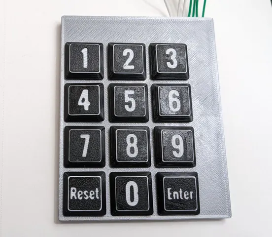
Another Parametric Matrix Keypad
prusaprinters
Update: I've done a minor redesign to make the keys a bit more responsive and to make assembly easier. The original file have been moved to a folder for reference purposes.This is the latest version of my matrix keypad design. It can be printed entirely in PLA or PETG. The only other material you need is 22AWG solid wire.The OpenSCAD code can generate a model for any size keypad by specifying the number of rows and columns, and the text for each key cap. You may also need to alter the text size of some keys in order to get the text to fit. There's an overall font setting, which I've got set to Oswald Bold. If you don't have that installed, the OpenSCAD will use the default font.PrintingThere's no need to print the entire keypad at once. I printed the base, cover and keys separately, in different colors, for example. You could also print some keys in different colors from the rest. To achieve contrasting text on the keys, change filament at 0.4mm and 0.8mm height.Construction(refer to the build image for steps)Strip wires and run through the horizontal (row) channels of the base. Make sure the wires stay flat against the base. The left ends might pop up. If they do, tack them down with glue or a filament pen.Run wires through the vertical (column) channels. These should rest on top of the bridges inside each key cavity.Snap the cover over the base. There's a notch in the upper right of the cover where the wires come out.Pop the keys through the cover and push down until they snap in place. It's a tight fit, so don't worry about forcing it.OperationPressing a key forces a column wire against a row wire, closing the connection on what amounts to a momentary push button. In order to read the keys, you'll need a microcontroller with at least enough configurable I/O pins to attach to all wires. Scanning the keys requires detecting which row and column wire are touching. The way I typically scan is:Set all row pins to floating input and all column pins to input with pullups.One at a time, set a row pin to output and force it “LOW”.With one row forced low, read each column pin.If a pin reads “LOW”, return the current row and column number. Note: The reason for setting the non-activated row pins to input is to avoid a short circuit when several keys are pressed at once.
With this file you will be able to print Another Parametric Matrix Keypad with your 3D printer. Click on the button and save the file on your computer to work, edit or customize your design. You can also find more 3D designs for printers on Another Parametric Matrix Keypad.
