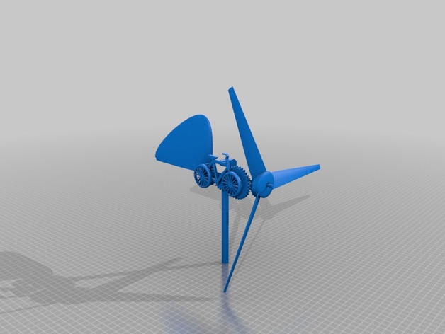
Anemometer with moving bicycle
thingiverse
Enjoy this anemometer, featured with a sleek bicycle design that's as fascinating to watch in motion. Each part has been carefully crafted by me, allowing it to rotate effortlessly even with gentle winds - I know it might seem useless, but it's definitely a fun novelty to observe. To ensure durability, the central shaft is made from high-quality carbon fiber, eliminating any potential issues that might arise from using PLA material. In order for the anemometer to move freely around its axis, a ball bearing is necessary - and another one is also required for the central blade. I used Autodesk Fusion 360 to design the gears, while all other components were created with Blender. To see the anemometer in action, simply click on this link: https://youtu.be/IMhXD53sVK4. Before you begin assembling the anemometer, it's a good idea to polish all holes and gears - the quality of your 3D printing will determine how smooth the operation is. To start building the anemometer, begin by putting together 01-Blade_base and 02-Blade (three pieces). Place a ball bearing in the rear hole and attach the 03-Blade_base gear using glue, just as shown in the provided image. A shaft with a diameter of 4mm and a length of 16cm will be needed; you can use any material you prefer - I opted for carbon fiber. As an added lock to prevent the blade from moving too freely, I used a clothespin typically found on RC cars. Next, insert 09-support into the shaft followed by 10-upper_pivot in its center. With that complete, you can now put in 12-rudder - apply some glue to ensure it doesn't shift out of place. You'll also need a ball bearing under 10-upper_pivot and another beneath that which should be positioned inside 11-bottom_pivot, a separate rod measuring at least 16cm tall. With those steps complete, you can proceed to assemble the bicycle separately. Begin by inserting 04-Chassis_bicyclette, making sure all holes are polished smooth, and attach 08-Front_gear in the front hole - on the opposite side, insert 05-Wheel, securing it with a toothpick. Performing the same operation at the rear using 06-rear_gear and 05-wheel will result in a smooth operation of your bicycle. Once complete, place 07-Central_gear into the central hole followed by 13-Pedal. Now that your bicycle is built, double-check to ensure all gears are operating freely without any obstacles or excessive force. Place the completed bicycle into 09-support, positioning it according to the provided image (make sure the joint is at the center of the bike). Apply a slight angle of counterclockwise inclination from above. Assemble the blade so that 08-Front_gear aligns closely with 03-Blade_base gear - and ensure smooth operation by watching for any sign of interference. Once you're satisfied that everything's in order, apply glue to 09-support. With that final step completed, enjoy the simple yet mesmerizing movement of your bicycle anemometer as it dances with the wind, albeit aimlessly.
With this file you will be able to print Anemometer with moving bicycle with your 3D printer. Click on the button and save the file on your computer to work, edit or customize your design. You can also find more 3D designs for printers on Anemometer with moving bicycle.
