Amazon Echo Flex Accessory Enclosure
prusaprinters
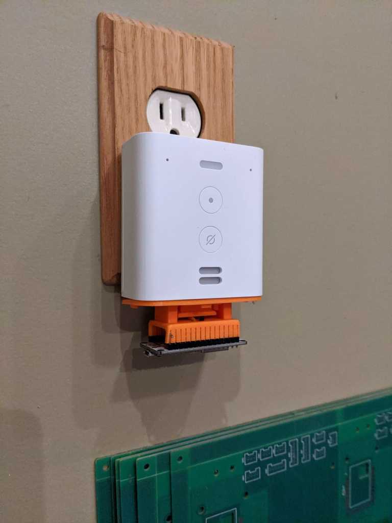
<p>The Amazon Echo Flex is a outlet-mounted Alexa device that's small, cheap, and--most relevant to makers: has a USB port on the bottom that is designed to power add-on accessories. Amazon currently makes a LED nightlight, motion sensor, and a digital clock that is designed to plug into this port. I wanted an enclosure that I could use to both protect and power my own ESP8266 Ardunio project.</p> <p>==================<br/> Printed Components</p> <ol> <li>Enclosure</li> <li>Lid</li> <li>Microcontroller saddle</li> <li>Retaining clip</li> </ol> <p>==================<br/> Other Parts Needed</p> <p>In addition to printing the components, you will also need to source the following parts for assembly:</p> <ul> <li>(4) M2 x 8mm heat-set threaded inserts</li> <li>(4) M2 x 8mm screws with countersunk heads (I prefer hex heads but any head will do, as long as it's countersunk. If you use hex heads, you'll also need a 1mm allen wrench.)</li> <li>(1) USB-A male PCB connector (If you don't purchase this exact product, please review the dimensions in the mechanical diagram in the project images to verify that you've got the right kind.)</li> <li>Some small-gauge (28 AWG or so) hook-up wire.</li> <li>Your microcontroller of choice. The included component is for a dev board that uses a 2x10 pin configuration (or shorter) with 0.1" headers. I'm using a NodeMCU ESP8622-based board because it's cheap and works with ESPHome, but almost any 5V powered dev board with this form factor will work. In the summary section below I recommend some tips for adapting this design for use with other boards.</li> </ul> <p>==================<br/> Assembly</p> <p>(Yes, I've written 10 steps... but this is should only take about two minutes to put together)</p> <ol> <li>Solder two lengths of wire, a couple inches long each, to the power pins on the USB plug. Looking at the plug from the backside (solder lugs facing you) and the white plastic spacer inside the connector facing towards the floor, the positive (5V DC) pin is to the far left and the ground pin is to the far right. Please double check against <a href="https://en.wikipedia.org/wiki/USB#/media/File:USB.svg">this image</a>. The "+" and "-" signs are also embossed on the inside of the lid.</li> </ol> <ol> <li>Insert the USB connector into the enclosure lid with the soldered wires facing up. The small metal prongs in the USB connector will face towards you. The top of the connector will be nearly flush to the lug on the lid.</li> </ol> <ol> <li>Insert the retaining clip so the tab on the clip engages the small slot under the metal prongs. Be aware that tab is not in the middle of the clip. You may need to flip it over to properly lock the USB plug into place.</li> </ol> <ol> <li>Double check that the USB connector is firmly installed and that retaining clip is properly seated. Once you install the microcontroller saddle in the next step, it will be nearly impossible to reseat the USB connector.</li> </ol> <ol> <li>Route the power wires up through the slot in bottom of the microcontroller saddle.</li> </ol> <ol> <li>Align the holes in the bottom of the saddle over the compression pins on the lid and gently, but firmly, press straight down. The saddle will snap into place. This is a permanent connection. </li> </ol> <ol> <li>The small slots between the pins in the saddle may contain filament stringing because they're so narrow. I recommend that you gently run an exacto knife or razor blade in between each slot to clear out any strands.</li> </ol> <ol> <li>Strip, cut to length, and insert the positive and ground wires into the proper saddle slots according to your board's pinout. The wires will traverse each pinhole perpendicular to the headers. The wires are held in the saddle and in contact with the microcontroller pins via friction and can be a bit tricky to insert. I recommend that you very lightly tin the end of the wires and then squeeze them flat with a pair of needle-nose pliers.</li> </ol> <ol> <li>Gently insert the dev board into the saddle, being careful not to dislodge the wires.</li> </ol> <ol> <li>Use a soldering iron to install the heat set inserts into the enclosure and then screw the lid on. Plug the Echo into the wall and you're done!</li> </ol> <p>==================<br/> Summary</p> <p>A microcontroller in an enclosure by itself isn't all that useful. There is a bit of space inside at the bottom in which you could drop in a small sensor, LED, etc. But I expect that most makers printing this will want to remix the enclosure for their specific needs. The point of this project for me was to solve the challenge of securely mounting the USB connector and microcontoller using an easily printable, support-free design.</p> <p>I've also designed this to allow the microcontroller saddle to be easily swapped out if you're using a microcontroller with a different footprint. An alternative saddle should be designed with a baseplate that's 2mm thick with a pair of 2mm holes, 30mm apart. The bottom of the holes need to be chamfered to properly mate to the compression pins on the lid.</p> <h3>Print instructions</h3><p>The retaining clip should be printed vertically to avoid the need for supports.</p> <p>I've this printed using bog standard PLA, 25% in-fill, and a 0.15mm layer height. I don't imagine that this design is overly picky with print settings with the possible exception of the screw holes. If they print slightly undersized though, they can be easily reemed with a drill bit or exacto knife.</p>
With this file you will be able to print Amazon Echo Flex Accessory Enclosure with your 3D printer. Click on the button and save the file on your computer to work, edit or customize your design. You can also find more 3D designs for printers on Amazon Echo Flex Accessory Enclosure.