Alien Flower
prusaprinters
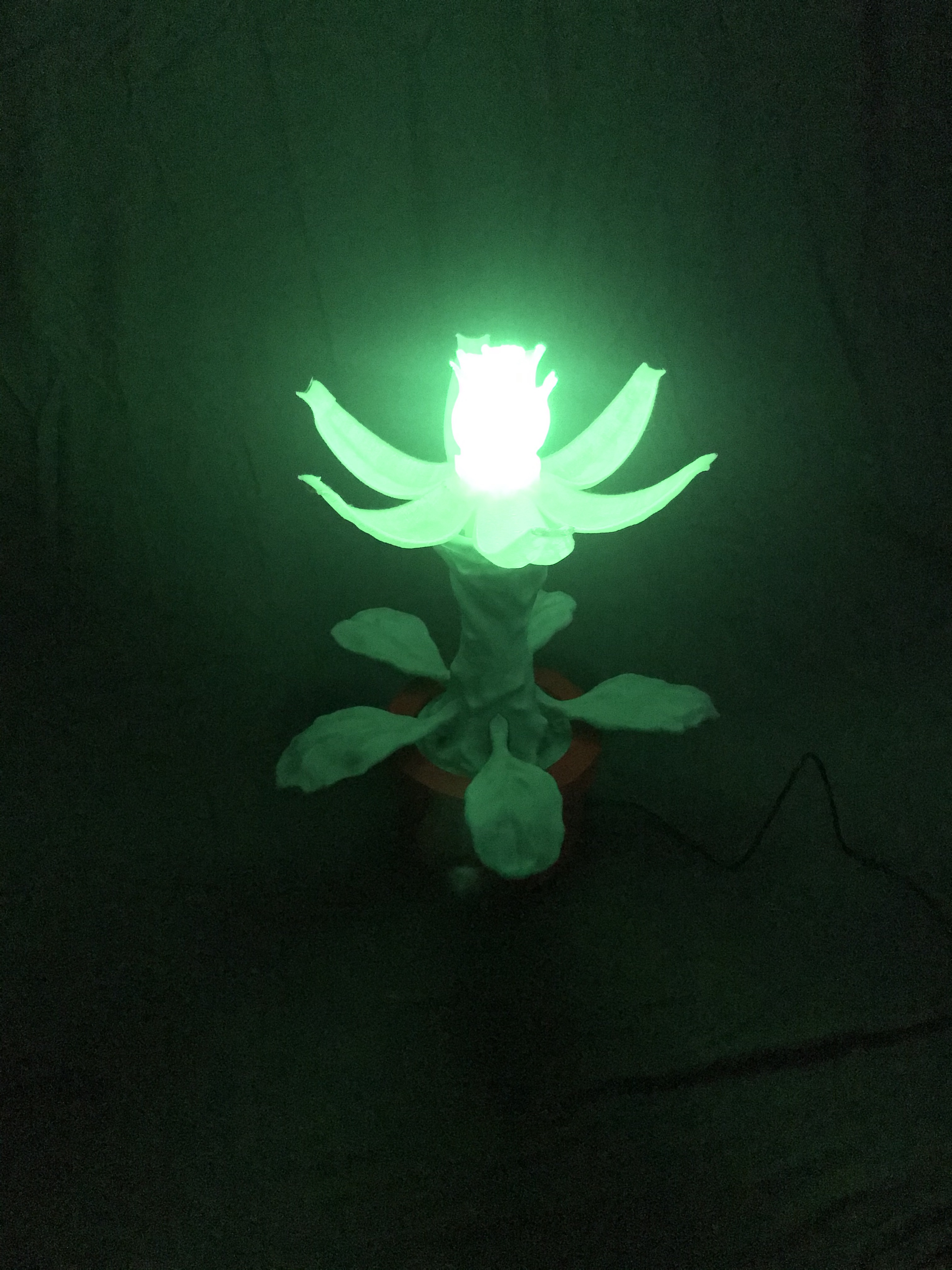
<p>Have you ever wanted a flower from another world? Maybe to impress your friends with your xenobiological prowess? If so, then this project is for you! This flower blooms in the dark, gently glowing from the inside of the petals. This is a great project if you want to see what making a larger printed assembly is like!</p> <h3>Print instructions</h3><p>Alien Flower Project Instructions</p> <p><h3>Introduction</h3><br/> This guide will show you in a step-by-step fashion how to print, assemble, program, and use, a light-sensitive alien looking blooming flower.</p> <p>This part would not have come to be without the help of my brother-in-law, Jesse, who provided a needed creative push, created concept art for the overall shape, sculpted the flower components to give them their organic look, and provided the Arduino. I'd also like to publicly thank my wife, who has been extremely patient over the last month.</p> <p><h3>Expected Skills</h3><br/> I've tried to make these instructions comprehensive and detailed. However, there are a few skills that are expected:<br/> Basic use of Arduino and electronics, including electronics safety<br/> Basic 3D printing knowledge</p> <p>Note: I will reference the Arduino and Arduino Uno throughout this guide. This project is not affiliated with Arduino, and they have not endorsed it in any way. I am using it here under the assumption that they will not have an issue with it. I'm not sure how to best give attribution per the creative commons share alike (<a href="https://creativecommons.org/licenses/by-sa/4.0/">BY-SA</a>) license, but I did reference the general Arduino reference material. If anyone from Arduino happens to read this and does have an issue with it, feel free to contact me via the Prusa website. And if anyone has questions about the build, feel free to contact me as well!</p> <p><h3>Materials</h3><br/> The following materials are required for this project:</p> <ul> <li>A 3D printer with a build volume of at least 160 x 160 x 160 mm (6.3 x 6.3 x 6.3 in)</li> <li>The STL files available at Prusa</li> <li>Approximately 200 meters of filament and a few days of print time. Some of the filament should be translucent. </li> <li>An Arduino Uno</li> <li>A light sensor (I used the GA1A12S202 Log-scale Analog Light Sensor from Adafruit) </li> <li>A Blue 9G Servo (you could use a different servo, however, you will need to figure out how to mount it)</li> <li>Mounting screws and wires for the electronics (I used male-to-male and male-to-female jump wires, so no soldering was required!</li> <li>A small screwdriver </li> <li>Needle-nose pliers or tweezers</li> <li>A small LED</li> <li>Electrical Tape</li> </ul><p><h3>Printing</h3><br/> All of the parts for this project are designed to be printed in the native STL orientation without supports. In addition, the parts for this print are designed to assemble as is, without any additional post processing. The tolerances are generally loose, which means everything that is supposed to fit should fit, even if printed on lower quality machines. That being said, 3D printing can be tricky business. I'm going to try and explain some of the issues I ran into, so that you can avoid them. I think most of those issues are related to my printer, so hopefully you have even better success!</p> <p>First, a few general comments. Some of these parts have large bases. I had some issues with prints warping, so I would recommend keeping that in mind. I was able to avoid this issue by changing the location of the print on my print bed (which says more about the evenness of heating in my bed than anything else). Also, be sure to keep the “elephants foot” issue in mind. It should not be a big issue, but some of the parts that fit a little closer together may be a bit tight. PrusaSlicer has a setting to address this. Of course, if all else fails, a quick spin with some sandpaper will fix that right up. Finally, many of these parts are designed to thread together. It may be worthwhile printing just the threaded sections of certain parts prior to committing to the entire print, just to make sure they will fit properly. They should, as they are quite loose, but no one likes to waste filament.</p> <p>I had two issues of note. The first was specific to the central petal assembly. This part consists of a simple print-in-place mechanism, where a central section is connected to six petals. I had some issues with overhang warping at the beginning of the petals, and also some generally sagging of the petals themselves. Everything finished all right, and everything is functional (and looks good!), but it's worth keeping an eye out for. I printed this part in PLA, and my printer does not having active cooling of the filament, which I think is the main issue. I'm guess that those of you with active cooling will not have an issue.</p> <p>The second issue was related to the Main Drive Screw. This is a relatively long, skinny part, and as such I had some cooling issues. This resulted in part of the threads being a bit mangled. Again, I think this is largely due to the lack of cooling for the PLA. Even with this issue, the rod still functioned well.</p> <p>There are five unique leaf designs. All should fit in the appropriate mounting sections of the stem.<br/> The parts Central Petal Assembly, Large Inner Petal, and Small Inner Petal, should all be printed in a translucent color. I used translucent yellow. The rest of the parts can be whatever you like, though an opaque filament will probably be best. I used a light green for the stem and leaves, and red for the pot.</p> <p>All parts were printed with the following parameters:</p> <ul> <li>0.2mm layer height</li> <li>2 outline shells</li> <li>3 base layers </li> <li>3-5 top layers </li> <li>5-15% rectilinear infill</li> </ul><p><h3>Servo Preparation</h3><br/> This projects relies on a motor that can spin continually both forward and backward. Most servos, however, do not allow for this operation by default. If you have a servo (such as the 9Gs I used) that is motion limited, it should be fairly simple to modify the servo to allow for continuous motion. It just requires a bit of finesse.</p> <p>It helps to understand how servos work in order to understand what this step is doing. As a very simple explanation, the device we call a servo or servomotor consists of a DC motor, a potentiometer, some gearing, and some circuitry. The potentiometer and motor are mechanically connected via the gears, and electrically connected via the circuit. When the servo is supplied with a pulse width modulated (PWM) signal, the circuit causes the motor to spin until the potentiometer is at the position that “matches” that signal, at which point the motor stops spinning. What we are doing in this modification is setting the servo to the neutral position, and then disconnecting the potentiometer from the gears. Now, when a signal is supplied that is different from the neutral signal, it will cause the motor to spin one way or the other. The potentiometer will never move, so the motor will never stop spinning. Voila! We have an inexpensive, already geared continuous motion device.</p> <p>The step-by-step process is below:</p> <ol> <li>Open the “Servo Modification” Arduino program, the source code for which can be found in Appendix A. Simply copy and paste that program into the Arduino IDE and upload it to your board. IMPORTANT: Make sure you understand what the code is doing BEFORE you upload it and run anything. I'm not responsible for any damaged boards, equipment, or persons. Proceed at your own risk.</li> <li>Connect the servo ground to the board ground. </li> <li>Connect the servo signal to pin 3. </li> <li>Connect the servo power to the board 5V supply. </li> <li>Make sure the servo is clear of any blockage. It can also be helpful to have one of the included servo mounts on the main drive, so that you can see the orientation of the servo. </li> <li>With all of the above properly connected, run the Servo Modification program. This will turn the servo all the way clockwise, followed by all the way counter-clockwise, and finally centered. Take note of the numbers that the program outputs to the serial monitor. These will be needed later. If your system is like mine, the full clockwise PWM value is 254, the full counter-clockwise value is 127, and the center value is 190. </li> <li>Now, carefully disconnect the servo from power. The best way to do this is to unplug the Arduino from your computer, so that the board is completely unpowered. Watch the servo to ensure that it does not move when the board powers down. </li> <li>Fully disconnect the servo from the board. </li> <li>Remove the servo attachment mount (the part that spins), being careful not to rotate the servo mechanism. It is important that the potentiometer stay in the position it was in when the Servo Modification program finished running. </li> <li>Open up the servo casing. On the 9G, this involves removing two screws from the back. </li> <img alt="Servo" height="600" src="https://media.prusaprinters.org/thumbs/inside/1280x960/media/prints/41620/images/413799_10c20f0f-4aba-4586-89c9-722c66297d12/servo-screws.jpg" width="500"/> <li>With the screws removed, you should be able to pull off the top of the servo case. This will reveal the gear train. </li> <img alt="Servo" height="600" src="https://media.prusaprinters.org/thumbs/inside/1280x960/media/prints/41620/images/413800_cf650f8d-7644-4c75-bd98-fc4cf2e1e8c7/servo-top-off.jpg" width="500"/> <li>Carefully move the “top” of the gear train. This is the gear that sticks out through the casing. You should be able to remove this without removing any other gears. It is important that you do not turn the potentiometer. </li> <img alt="Servo" height="600" src="https://media.prusaprinters.org/thumbs/inside/1280x960/media/prints/41620/images/413800_cf650f8d-7644-4c75-bd98-fc4cf2e1e8c7/servo-top-off.jpg" width="500"/> <li>Examine the gear you just removed. It should consist of a short, stubby section that sticks out through the casing, a wide section that interfaces with the next gear, and a long, narrow section. This long narrow section serves two purposes. It is the main rod for half of the gear train, and it connects to the servo. Part of the long narrow section is completely round, and the other part has two flats. These flats interface with the potentiometer, and are about 1/3 the length of the narrow section itself.</li> <li>Carefully cut off the flat section of the long, narrow rod. The cutting section of the needle-nose pliers are a good option for this. Be careful to keep as much of the rod as possible, while not leaving enough to touch the potentiometer. </li> <img alt="Servo" height="600" src="https://media.prusaprinters.org/thumbs/inside/1280x960/media/prints/41620/images/413797_56696762-175b-4bdc-b3df-5ddd3e9c6b85/servo-modified-gear.jpg" width="500"/> <li>Re-insert the modified gear, and reassemble the servo. </li> <li>Reconnect the servo to the Arduino, as it was connected before. Upload and run the “Servo Correction” program, in Appendix B. </li> <li>By default, the ServoControlPin value is set to 190, which should result in no servo movement. However, if the potentiometer moved during the modification process, this number may result in slight movement. Adjust this variable up or down, and observe how the potentiometer moves. I had to adjust my servo center to be between 185 and 188. Anything higher or lower than those values resulted in movement. This is also a good time to see how the further you get from the center, the faster and more powerfully the servo will spin. </li> </ol><p><h3>Flower Assembly</h3><br/> At this point, everything should be ready to assemble the flower. I am going to include the electronics in the below assembly process. However, it might be worthwhile to do a dry-run first. Assemble all the mechanical components as below, and get a sense of how everything is fitting together. I would recommend testing out the main drive screw and verifying that nothing is binding. If there is any major binding, you may need to sand down some edges. However, that should not be required.</p> <p><u>Preparing the Flower Pot</u></p> <ol> <li>Start by finding the Pot – Lower part. <img alt="Servo" height="600" src="https://media.prusaprinters.org/thumbs/inside/1280x960/media/prints/41620/images/413789_8d48fd89-329e-4b3f-bac8-b48c8a0e99ae/pot-lower.jpg" width="500"/> <li>The inside of this part is designed to accept the Arduino Uno. Place the Uno on the mounting section, and secure it with two screws. The USB port and power port should line up with the openings in the pot. There a pre-printed mounting holes that are designed to align with the Arduino holes. Those may need to be opened slightly by hand, but small screws should be able to go in without issue (though the plastic will move a bit).</li> <img alt="Servo" height="600" src="https://media.prusaprinters.org/thumbs/inside/1280x960/media/prints/41620/images/413793_2d92b6c0-8768-47f3-bb15-861d3f88fd43/pot-lower-with-arduino.jpg" width="500"/> <li>Connect your light sensor to the Arduino as appropriate. I used pin A0 as the sensor input, and the 3.3 V supply for power. </li> <li>Thread the sensor through the USB hole in the pot. Make sure there is enough slack to move the sensor out of the way for uploading software. When the USB port is not in use, the sensor can be snugged up against it. This ensures that the sensor receives enough light to trigger the flower. </li> <img alt="Servo" height="600" src="https://media.prusaprinters.org/thumbs/inside/1280x960/media/prints/41620/images/413792_6dea1457-2828-4b70-8215-9f8d75176bb1/pot-lower-with-sensor.jpg" width="500"/> <li>Next, find the Pot – Upper section. </li> <li>The inside of the pot is designed for the 9G servo. Position the servo such that the mounting tabes overlay the pre-printed mounting holes, and the center of the servo is aligned with the center of the pot. The servo wire should hang freely through the mounting structure. </li> <img alt="Servo" height="600" src="https://media.prusaprinters.org/thumbs/inside/1280x960/media/prints/41620/images/413796_7bc9a477-fb0e-4c07-a138-b65402faff21/pot-upper-with-servo.jpg" width="500"/> <li>Find the Servo Mate component. The bottom of this part consists of two concentric spirals. In theory, these will allow you to position any servo mount and have it be close to center. In this case, I used the the longest mount that came with the 9G. Mount that component to the bottom of the Servo Mate, using the provided screws. </li> <img alt="Servo" height="600" src="https://media.prusaprinters.org/thumbs/inside/1280x960/media/prints/41620/images/413795_06937ac9-6e45-4033-80ab-693fd300390f/servo-mate-with-servo-mount.jpg" width="500"/> <li>Take the Servo Mate with the servo mount attached, and carefully place it on the servo itself. There is a hole through the Servo Mate that will allow you to screw the assembly to the servo. Do this now. Make sure the screw is tight, but do not strip it. This is plastic after all! </li> <img alt="Servo" height="600" src="https://media.prusaprinters.org/thumbs/inside/1280x960/media/prints/41620/images/413794_3dd4f563-774f-4d21-9461-50a5245eddf2/servo-mate-on-servo-with-screw-driver.jpg" width="500"/> <li>Be careful with the setup as it currently is. The link between the servo and the mate is delicate without the support of the lower stem. </li> <li>Get the Main Drive Rod and the Lock Nut. </li> <li>Screw the Lock Nut onto one side of the Main Drive Rod. </li> <img alt="Servo" height="600" src="https://media.prusaprinters.org/thumbs/inside/1280x960/media/prints/41620/images/413784_0c721134-4daa-4bd9-98f0-13646d791c6c/drive-rod-with-nut.jpg" width="500"/> <li>Screw the Main Drive Rod into the Servo Mate. </li> <li>Tighten the Lock Nut against the top of the Servo Mate. This locks all the components together, and allows the servo to actuate the petals. Make sure that the Servo Mate and the Lock Nut are aligned. Otherwise, it may bind in the stem. </li> <img alt="Servo" height="600" src="https://media.prusaprinters.org/thumbs/inside/1280x960/media/prints/41620/images/413781_786ba9e9-7a2b-45b9-9880-0c0621a29262/drive-rod-mounted.jpg" width="500"/> </li></ol><p><u>Preparing the Stem</u></p> <ol> <li>Feed Two male-to-female (ideally a red one and a black one) jumper wires through the small routing hole in the Stem – Lower part. Use the hole that is on the same side as the routing track. They will probably need to be fed one at a time. </li> <img alt="Servo" height="600" src="https://media.prusaprinters.org/thumbs/inside/1280x960/media/prints/41620/images/413803_1cdb43ac-97e7-4094-8c48-1b05c37f476d/stem-lower-with-wires-top.jpg" width="500"/> <li>Assemble the Stem – Upper and Stem – Lower components by threading them together. </li> <li>Route the wires through the Stem – Upper, making sure to not to pull the wires all the way up. </li> <img alt="Servo" height="600" src="https://media.prusaprinters.org/thumbs/inside/1280x960/media/prints/41620/images/413804_0c71a746-4db2-4196-889c-8221f2267fe1/stem-assembly-with-wires.jpg" width="500"/> <li>Feed the two jumper wires through the side holes of the Petal Pusher and out through the top. </li> <img alt="Servo" height="600" src="https://media.prusaprinters.org/thumbs/inside/1280x960/media/prints/41620/images/413790_01768528-3242-4b2d-821a-c90adc893e30/petal-pusher-with-wires.jpg" width="500"/> <li>Wrap the tips of the female ends together with a bit of electrical tape, and snug it into the hole in the thread. Make sure to keep track of which end is positive (red) and which end is ground (black). </li> <li>Insert the LED into the wire leads, taking care that both leads are fully engaged. If you want, trim the LED leads a bit so that it sits a bit lower. This will make the LED bulb less visible in the final flower. Set this part aside for now. </li> <img alt="Servo" height="600" src="https://media.prusaprinters.org/thumbs/inside/1280x960/media/prints/41620/images/413791_9111f650-df21-4ac2-a144-45bfcb78949a/petal-pusher-with-led.jpg" width="500"/> <li>Get the Central Petal Assembly, the Large Inner Petal, and the Small Inner Petal. </li> <li>Attach the Small Inner Petal to the Central Petal Assembly by snapping the Small Inner Petal in place. The Central Petal Assembly has two receptacles for the inner petals. They can be found inside the support structure holding up the small petal that is fixed to the central assembly. The Small Inner Petal goes on the opposite side of the permanently fixed petal. This part should just snap in, but of course, be careful. </li> <img alt="Servo" height="600" src="https://media.prusaprinters.org/thumbs/inside/1280x960/media/prints/41620/images/413778_d914692a-775c-45fd-b94b-53927c593c4b/central-petal-assembly-with-small-petal.jpg" width="500"/> <li>Repeat the above process for the Large Inner Petal. This part is opposed to the Small Inner Petal. </li> <img alt="Servo" height="600" src="https://media.prusaprinters.org/thumbs/inside/1280x960/media/prints/41620/images/413779_da7dd8e7-4f77-4550-9a70-64d1eda86944/central-petal-assembly-with-large-petal.jpg" width="500"/> <li>Retrieve the Stem Assembly with the LED, and thread the Central Petal Assembly on to the Petal Pusher. Take care to not damage the LED. Also make sure to leave a bit of slack in the wires at the top of the Stem, to allow for easy movement up and down. </li> <img alt="Servo" height="600" src="https://media.prusaprinters.org/thumbs/inside/1280x960/media/prints/41620/images/413805_ee07fa0d-1971-4904-be37-de2c0f515e06/showing-wire-slack.jpg" width="500"/> <li>This is a good opportunity to ensure the petals are freely moving. They are designed to fall under their own weight. If you hold the assembly with the LED facing up, the petals should open. If you hold the assembly the LED facing down, the petals should close.</li> <li>If you are going to be mounting the leaves with the Leaf Bolts, this would be the time to insert the leaves and bolts. The process for doing this is simple – just insert the leaves into the receptacles in the stem, and then snug down the bolts from the underside of the stem. However, I found that the leaves did not need any extra security, so I will insert them later. </li> <li>Slide the entire Stem Assembly onto the Upper Pot Assembly, ensuring that the Servo Mate and Lock Nut are properly aligned with the Stem – Lower. </li> <img alt="Servo" height="600" src="https://media.prusaprinters.org/thumbs/inside/1280x960/media/prints/41620/images/413785_fa508c66-be3f-4f7e-9862-7a79f07e7922/flower-without-petals.jpg" width="500"/> <li>Screw the Stem Assembly into the Pot – Upper top, ensuring that the LED lead wires do not get stuck. </li> <img alt="Servo" height="600" src="https://media.prusaprinters.org/thumbs/inside/1280x960/media/prints/41620/images/413806_9caea116-64cb-431c-b1d2-a8a6ba105dc4/underside-of-pot-with-wires.jpg" width="500"/> <li>Extend each of the LED lead wires with two more male-to-female jumpers.</li> <li>If you want, you can reach inside the pot and manually turn the Servo Mate. Turning it one direction will cause the flower to bloom, and turning it the other way will cause the flower to close. It is a good idea to do this prior to uploading the program. Make sure the flower has full range of motion. </li> </ol><p><u>Final Wiring</u></p> <ol> <li>Extend the servo wires with three male-to-male jumpers. Try and keep the colors coordinated.</li> <li>At this point, you should have five wires coming out of the bottom of the Stem Assembly. The power and ground wires from the LED, and the power, ground, and signal wires from the servo.</li> <li>Bring the Main Assembly physically close to the Pot – Lower part with the Arduino. </li> <li>Connect the LED ground to the Arduino ground, and connect the LED power to pin 5. At this point, some of you might say “Wait a minute! You need a resistor on the positive side of that LED!” Well, I thought so too, but then I forget to put the resistor in and everything worked fine. However, if it would make you feel better, feel free to put a resistor in the line somewhere. You make need to do a bit of soldering though. </li> <li>Connect the servo ground to the Arduino ground, the servo power to the 5V supply, and the servo signal to pin 3. </li> <img alt="Servo" height="600" src="https://media.prusaprinters.org/thumbs/inside/1280x960/media/prints/41620/images/413782_7d47c0d1-5f6e-42db-8c40-e2bf60fe1a11/flower-with-wires.jpg" width="500"/> <li>Finally, carefully take the entire Main Assembly and place it in the Pot – Lower. The two parts should just nest in each other. On mine, you might see some threads. Those were from a previous design. The final model does not have those threads. I didn't print out the new model myself, but it should work just fine. </li> <li>If you haven't already, attach the leaves. This can be done by first inserting the top of the leaf mount (the pointed end), and the rotating down. It should just sit in place. </li> <img alt="Servo" height="600" src="https://media.prusaprinters.org/thumbs/inside/1280x960/media/prints/41620/images/413788_911c2ab4-dca3-497a-94aa-77441b8a2cf4/leaf-start.jpg" width="500"/> <img alt="Servo" height="600" src="https://media.prusaprinters.org/thumbs/inside/1280x960/media/prints/41620/images/413787_a823c8b0-d9b8-4b39-aab6-16e3a48edaa6/leaf-end.jpg" width="500"/> </ol><p>Congratulations! At this point, the assembly is complete. The next step is to upload the full program and test everything out.</p> <p><h3>Upload and Test Program</h3></p> <ol> <li>Connect the Arduino to your computer, making sure the light sensor is out of the way. </li> <li>Copy and upload the Blooming Flower Code, found in Appendix C. You will probably need to adjust the bloomSpeed, closeSpeed, and servoOff variables from the values that I have. </li> <li>The first step is to calibrate the light. The program will turn in the bloom direction for a few seconds, fully opening the flower. Then it will reverse direction for a few second and fully (or nearly) close the flower. Sometime, the petals can jam at this step. If this happens, simply restart the program and use your hand to guide the petals during the closing phase. At this point, LED will start blinking. This indicates that the flower is ready for calibration. </li> <li>The next step is to define the bloom position. While the LED is blinking, cover the light sensor with your hand. This will cause the flower to start blooming. When the flower is at your desired final position, remove your hand. The flower will record how long it took to bloom, and repeat that time for future bloom events. </li> <li>Once you remove your hand, the flower will close and assume normal operation. To test it out, try covering the sensor with your hand again. The flower should bloom! At this point, the flower will bloom when it is dark, and close when it is light. </li> </ol><p><h3>Troubleshooting</h3></p> <ul> As with most projects, there are some issues that you might run into. Here are some of the problems that I had, and how I dealt with them. <li>My flower is jammed in the blooming phase.</li> <ul> <li>This can happen for two fundamental reasons. Either the servo is not applying enough torque, or something has become stuck. If the servo is not applying enough torque, simply change the bloomSpeed variable to be further from the servoOff variable. Make sure you change the closeSpeed variable equally in the other direction, other wise the flower will not close fully after blooming. </li> <li>If servo torque is not the problem, then something must be jamming the mechanism. It might be that the Servo Mate, Lock Nut, and Main Drive Rod have become loose. If this is the case, you will need to disassemble the flower and correct it. It is also possible that the wires may be in the way. Make sure that everything is in the correct track. </li> </ul> <li>My flower is jammed in the closing phase.</li> <ul> <li>This can happen for the same reasons as above, and requires the same solutions. However, it can also happen during the initial calibration phase. This occurs because the Main Control Rod and the Petal Pusher are binding, likely because the Petal Pusher has been pushed all the way off the Rod. Also, if the Petal Pusher is not properly aligned with the tracks, it may get stuck. In either case, using your hand to guide the petals should solve this issue. </li> </ul> <li>My flower is not responding as expected to the changing light.</li> <ul> <li>This happened to me when the light sensor was not getting enough light, or the change in light was not extreme. You can try adjusting some of the parameters in the program that control the light threshold, though that will require some coding knowledge. Your best bet is to set up the flower in a bright, well lit room, and make sure the light sensor is not in shadow. </li> </ul> <li>Not all of the petals are unfolding during the bloom process. </li> <ul> <li>This can happen when the flower has been pulled down tightly in the closed position. Of course, you can just knock the petal down yourself. However, if you are still having issues, a recalibration might help (unplug the Arduino and plug it back in). Finally, you might want to remove the petal assembly and make sure everything can move freely. </li> </ul> </ul><p><h3>Appendix A – Servo Modification Program </h3><br/> //Define pin variables<br/> int servoControlPin = 3;</p> <p>//Define Servo Variables<br/> int servoCenterPWM = 0; //This is used to command the servo to the center using the OWM signal<br/> int PWMDutyCycleMax = 254; //Set the highest value the servo will accept<br/> int PWMDutyCycleMin = 0; //This variable will be used to store the 50% duty cycle value</p> <p>void setup() {<br/> //Set pin modes<br/> pinMode(servoControlPin, OUTPUT);</p> <p>//Start serial connection<br/> Serial.begin(9600);</p> <p>//One the Arduino Uno, pin 3 is a PWM pin that oscillates at 500 hz, which translates to a period of 2 ms.<br/> //The 9G servo accepts signals between 1 and 2 ms, so this range is ideal.<br/> //The PWM pins accept inputs from 0 to 255, where 0 is fully off, and 255 is fully on.<br/> //Therefore, the 9G servo should turn almost all the way in one direction at 254 (the largest non-constant<br/> //signal, and completely the other way at 255/2, which is ~127.</p> <p>Serial.print("The maximum clockwise rotation PWM value is: ");<br/> Serial.print(PWMDutyCycleMax); //Print for debugging<br/> Serial.println();</p> <p>//Calculate the 50% duty cycle, which is one servo extreme<br/> PWMDutyCycleMin = PWMDutyCycleMax/2;<br/> Serial.print("The maximum counter-clockwise rotation PWM value is: ");<br/> Serial.print(PWMDutyCycleMin); //Print for debugging<br/> Serial.println();</p> <p>//calculate the servo center<br/> servoCenterPWM = (PWMDutyCycleMax + PWMDutyCycleMin)/2;<br/> Serial.print("The center PWM value is: ");<br/> Serial.print(servoCenterPWM); //Print for debugging<br/> Serial.println();</p> <p>analogWrite(servoControlPin, PWMDutyCycleMin); //Command the servo all the way one direction<br/> delay(5000);</p> <p>analogWrite(servoControlPin, PWMDutyCycleMax); //Command the servo all the way the other<br/> delay(5000);</p> <p>analogWrite(servoControlPin, servoCenterPWM); //Command the servo to the center<br/> }</p> <p>void loop() {<br/> //Nothing goes here!<br/> }</p> <p><h3>Appendix B – Servo Correction Program </h3><br/> //Define pin variables<br/> int servoControlPin = 3;</p> <p>//Define Servo Variables<br/> int servoCenterPWM = 190; //ADJUST THIS VARIABLE until the servo does not move.<br/> //Start with the center value from the Servo Modification program</p> <p>void setup() {<br/> //Set pin modes<br/> pinMode(servoControlPin, OUTPUT);</p> <p>//Start serial connection<br/> Serial.begin(9600);</p> <p>analogWrite(servoControlPin, servoCenterPWM); //Command the servo to the center<br/> }</p> <p>void loop() {<br/> //Nothing goes here!<br/> }</p> <p><h3>Appendix C – Blooming Flower Code</h3><br/> //Define pin variables<br/> int lightSensorPin = A0;<br/> int servoControlPin = 3;<br/> int ledOnePin = 5;</p> <p>//Define control variables<br/> double bloomSpeed = 175; //This opens the flower. It should be as slow as possible while still turning the servo<br/> double closeSpeed = 205; //This closes the flower. It should be as slow as possible while still turning the servo<br/> //Both of the speed variables should be approximately equal from the center, to ensure that the servo turns at the<br/> //same speed both ways.<br/> double servoOff = 190; //This is the signal that turns off the servo. Set this to the value found in Servo Correction</p> <p>//Define other variables<br/> long lightSensorValue = 0;<br/> double lightRunningAverage = 0;<br/> int bloomToggle = 0; //0 is closed, 1 is open<br/> int ledValue = 0; //This defines the current LED brightness<br/> int ledCurrentDelay = 0; //This defines the intermediate values for fading the LED<br/> double lightHigh = 0;<br/> double lightLow = 0;<br/> double bloomCountTotal = 0; //This many cycles is required to take the flower from fully closed to fully open<br/> double bloomCountTemp = 0;<br/> double bloomStart = 0; //units of milliseconds<br/> double bloomTime = 0; //units of seconds<br/> double startTime = 0; //units of milliseconds<br/> double curTime = 0; //units of milliseconds</p> <p>void setup() {</p> <p>//Set pin modes<br/> pinMode(lightSensorPin, INPUT);<br/> pinMode(servoControlPin, OUTPUT);<br/> pinMode(ledOnePin, OUTPUT);</p> <p>//Start serial connection<br/> Serial.begin(9600);</p> <p>//Calibration Section</p> <p>//First, open the flower. This ensures that in the event of a program reset,<br/> //the servo doesn't start in a stalled position<br/> //Set the servo control to the bloom direction (less than 190) and wait for 5 seconds<br/> //The first servo is set to a much lower value, to provide more current. This will help unstick<br/> //the flower is ther parts have jammed at all.<br/> analogWrite(servoControlPin,140);<br/> delay(250);<br/> analogWrite(servoControlPin,bloomSpeed);<br/> delay(7000);</p> <p>//Next, gradually closer the flower in preparation of measuring the bloom time.<br/> //Set the servo control to the close direction (greater than 190) and wait for 5 seconds<br/> analogWrite(servoControlPin,closeSpeed);<br/> delay(10000);</p> <p>//Turn off servo control<br/> analogWrite(servoControlPin,servoOff);</p> <p>//Next, enter a loop that blinks the LED and waits for the user to trigger the "open" cycle, by covering the<br/> //access ports</p> <p>while (bloomTime == 0) {<br/> analogWrite(ledOnePin,255);<br/> delay(100);<br/> analogWrite(ledOnePin,0);<br/> delay(100);</p> <p>//Take running average of light reading<br/> lightSensorValue = 0;<br/> for (int i = 1; i < 2000; i++) {<br/> lightSensorValue = lightSensorValue + analogRead(lightSensorPin);<br/> lightRunningAverage = lightSensorValue/i;<br/> }</p> <p>Serial.print("Cur: ");<br/> Serial.print(lightRunningAverage);<br/> Serial.println();</p> <p>//Record the high value of the light input<br/> if (lightRunningAverage > lightHigh) {<br/> lightHigh = lightRunningAverage;<br/> }</p> <p>//set the low value to be equal to the high value<br/> lightLow = lightHigh;</p> <p>//Set the start time, incase the user has covered the sensor for calibration<br/> bloomStart = millis();</p> <p>//Check to see if the light input has changed by 5. This is a significant change.<br/> //Assume this change is taking pklace because the user has placed their hand over the light ports<br/> while (lightHigh - lightRunningAverage > 5) {<br/> //Set the low value based on the user covering the opening. This should be close to the darkest the<br/> //sensor will see<br/> //Record the low value of the light input<br/> if (lightRunningAverage < lightLow) {<br/> lightLow = lightRunningAverage;<br/> }</p> <p>//This will jerk the petals, but only at the start<br/> if (bloomToggle == 0){<br/> analogWrite(servoControlPin,140);<br/> delay(250);<br/> bloomToggle = 1;<br/> }</p> <p>analogWrite(servoControlPin,bloomSpeed);<br/> //We still need to find the running average of the light reading, so continue taking that.<br/> lightSensorValue = 0;<br/> for (int i = 1; i < 2000; i++) {<br/> lightSensorValue = lightSensorValue + analogRead(lightSensorPin);<br/> lightRunningAverage = lightSensorValue/i;<br/> }<br/> bloomTime = millis() - bloomStart;<br/> }<br/> //Once the user has finished calibration, turn off the motor<br/> analogWrite(servoControlPin,servoOff);<br/> }<br/> //Set the servo control to the close direction (greater than 190) and wait for the bloomTime<br/> analogWrite(servoControlPin,closeSpeed);<br/> delay(bloomTime);<br/> analogWrite(servoControlPin,servoOff);<br/> bloomToggle = 0;<br/> }</p> <p>void loop() {</p> <p>// Normal Operation Section<br/> //Take running average of light reading</p> <p>//------------------------------------------------------<br/> lightSensorValue = 0;<br/> for (int i = 1; i < 2000; i++) {<br/> lightSensorValue = lightSensorValue + analogRead(lightSensorPin);<br/> lightRunningAverage = lightSensorValue/i;<br/> }</p> <p>//Record the high value of the light input<br/> if (lightRunningAverage > lightHigh) {<br/> lightHigh = lightRunningAverage;<br/> }</p> <p>//Record the low value of the light input<br/> if (lightRunningAverage < lightLow) {<br/> lightLow = lightRunningAverage;<br/> }</p> <p>Serial.print("High: ");<br/> Serial.print(lightHigh);<br/> Serial.println();</p> <p>Serial.print("Cur: ");<br/> Serial.print(lightRunningAverage);<br/> Serial.println();</p> <p>Serial.print("Low: ");<br/> Serial.print(lightLow);<br/> Serial.println();<br/> //------------------------------------------------------</p> <p>//Check to see if the running average has come within 20% of the spread between the high and<br/> //low values and the low value. If so, start the bloom process.<br/> if (lightRunningAverage < (lightLow + (0.2*(lightHigh-lightLow))) && bloomToggle == 0) {<br/> //Start the blooming process<br/> analogWrite(servoControlPin,140);<br/> delay(250);</p> <p>//Get the start time for the while loop<br/> startTime = millis();<br/> curTime = millis()-startTime;<br/> while (curTime < bloomTime){<br/> //Turn the servo on<br/> analogWrite(servoControlPin,bloomSpeed);</p> <p>//Turn on the LED a little bit at a time.<br/> ledValue = 255*pow((curTime/bloomTime),2);<br/> analogWrite(ledOnePin,ledValue);</p> <p>//Update the current time<br/> curTime = millis()-startTime;<br/> }<br/> //Stop the blooming<br/> analogWrite(servoControlPin,servoOff);<br/> bloomToggle = 1;<br/> }</p> <p>//Check to see if the running average has come within 20% of the spread between the<br/> //high and low values of the high value. If so, start the close process.<br/> if (lightRunningAverage > (lightHigh - (0.3*(lightHigh-lightLow))) && bloomToggle == 1) {<br/> //Start the closing process</p> <p>//Get the start time for the while loop<br/> startTime = millis();<br/> curTime = millis()-startTime;<br/> while (curTime < bloomTime){<br/> //Turn the servo on<br/> analogWrite(servoControlPin,closeSpeed);</p> <p>//Turn on the LED a little bit at a time<br/> ledValue = 255*(1 - curTime/bloomTime);<br/> analogWrite(ledOnePin,ledValue);</p> <p>//Update the current time<br/> curTime = millis()-startTime;<br/> }<br/> analogWrite(servoControlPin,servoOff);<br/> analogWrite(ledOnePin,0);<br/> bloomToggle = 0;<br/> }<br/> }</p>
With this file you will be able to print Alien Flower with your 3D printer. Click on the button and save the file on your computer to work, edit or customize your design. You can also find more 3D designs for printers on Alien Flower.