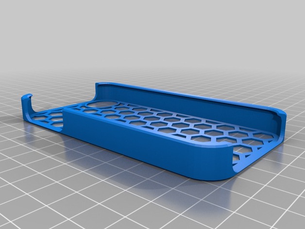
Alec
thingiverse
This is a set of commands for G-Code (Geometric Code) format, used to instruct Computer Numerical Control (CNC) machines or other CNC equipment on how to fabricate items from raw material through machining and post-processing. The structure provided doesn't specify the exact G-Code operations because it mixes metadata related to a 3D modeling session in Autodesk Fusion360 with parameters that could potentially influence what commands are written into a final G-code file. However, we can interpret this to understand what's involved: 1. **Design Parameters**: It specifies design parameters for an enclosure (or possibly other 3D object based on how these values map) in what looks like Fusion 360's Design workspace export. This section indicates specific settings for features like stencil mirroring, edge chamfering, corner resolution, port lengths and widths, camera positioning (on the back of an assumed phone), pattern overlap, and custom fillets and ports. 2. **3D Coordinate Sets**: The first `M67 P123...` line, with long sets of numbers, likely refers to multiple locations defined for cutting paths. These lines would define points in 3D space, each specifying an endpoint or startpoint for the cutting operation (like M97 is used for tool offsets but this is beyond standard). The list after seems related to mapping a part of those coordinates for possibly different design operations on it, indicated by indexing with consecutive numbers starting from 0 and going up to what might indicate number of sides or cuts needed based on specific indexes used in stencil creation tools or the custom settings given at top of text. The last two brackets, [[coordinates]] with 127 pairs after seem more about where various tool heads will sit within machine for particular operations defined next (the line "stencil_mirror = 0"). However there isn’t information regarding which particular cutting tools these relate to, or how they will apply forces given custom resolutions as stated later ("custom_corner_resolution" etc.). In many CNC designs however such indexing would be a quick identifier during process development in pre-operational software setup (like Autodesk itself), allowing users to set and test each unique action individually. 3. **Pattern Overlap Settings**: Some commands suggest control over whether cuts for the tool go through each point exactly once, which helps save material as parts grow larger based on those settings and other custom top features or corners designed ("custom_back_extra_port_y_position"). This G-Code seems specifically prepared for making one part where a mirror reflection across specified lines creates some identical shapes for each design choice provided – this would then reflect a tool operation pattern to avoid manual calculation every time as is commonly used within pre-compiled tools of modern software environments which use visual editors instead manual code entry today often leaving more details on final cut accuracy & exact edge geometry down at the programming layer based in that visual work flow where users typically do very small edits & can review & test individual layers.
With this file you will be able to print Alec with your 3D printer. Click on the button and save the file on your computer to work, edit or customize your design. You can also find more 3D designs for printers on Alec.
