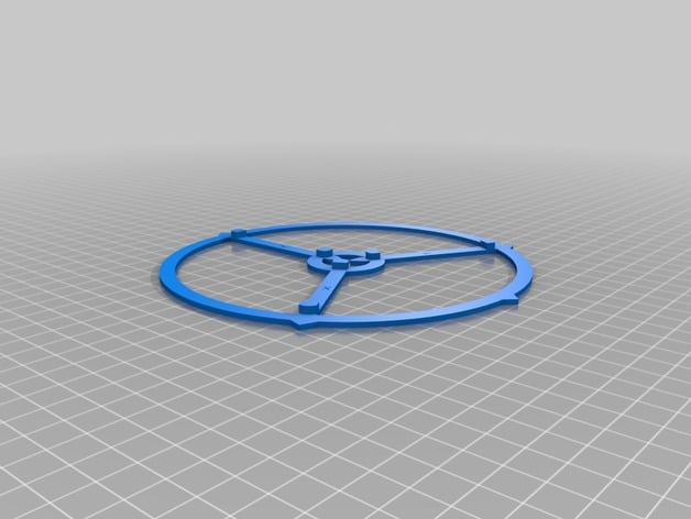
Advanced Delta Printer Calibration (tower position + individual diagonal rod)
thingiverse
The provided text appears to be a set of instructions for adjusting the print size on a Delta 3D printer. The adjustments are required because of irregularities in the dimensions of the printed object. This can occur when the calculated dimensions are used instead of the actual measured dimensions. **Calculating Diagonal Rod Size Correction** * First, identify the most accurate measurement from x, y, and z size. * Use this value to correct the `DELTA_DIAGONAL_ROD` value in the `configuration.h`. * Then, calculate each rod length individually using its corresponding x, y, or z value: * \(x\) size correction: \(60.25 \div 60\) * \(y\) size correction: \(60.31 \div 60\) * \(z\) size correction: No adjustment (this measurement should already be accurate) **Delta Tower Angles** * Use the provided math operations for `delta_tower1_x` and `delta_tower1_y`. * Note that there's an inconsistency with the sign in these variables - delta\_tower2\_x uses sin\_61, but it was assumed to use COS\_61 which corresponds to SIN\_59. There's also missing information on how the angle value is selected between cos and sin. * Apply a similar calculation for `delta_tower2_x` and `delta_tower2_y`. **Delta Rod Calculation in Marlin** 1. Search for the function "calculate_delta" in marlin\_main.cpp and modify it as described: ```c delta[X_AXIS] = sqrt( (delta_diagonal_rod_2_x) - sq(delta_tower1_x-cartesian[X_AXIS]) - sq(delta_tower1_y-cartesian[Y_AXIS]) ); delta[Y_AXIS] = sqrt( (delta_diagonal_rod_2_y) \ - sq(delta_tower2_x-cartesian[X_AXIS]) \ - sq(delta_tower2_y-cartesian[Y_AXIS]) \ ); delta[Z_AXIS] = sqrt( (delta_diagonal_rod_2_z) - sq(delta_tower3_x-cartesian[X_AXIS]) - sq(delta_tower3_y-cartesian[Y_AXIS]) ); ``` In the corrected lines, add `(delta_diagonal\_rod \* 60.25/60)`, `(`delta_diagonal\_rod`\) * (60.31 / 60))`, and `(`delta\_diagonal\_rod'`\\`) respectively after "delta\_diagonal\_rod". Note that it would seem better to adjust each of these three lines using the appropriate calculated value instead. To fix tower angles add a call like delta_tower2\_x= SIN\_61* delta_radius \* (60.31/60); to define tower1 and similar for all three towers. To conclude: 1\. In case you're not using version 1.0.2 of the firmware or Marlin in general, look into using Marlin v1.0.3, it includes bug fixes which can cause errors during these calculations. It looks like a manual process, which may take time if the errors are quite big. You might need to adjust and re-calibrate as you go through different prints, and keep updating your calibration file according to the output from your slicer.
With this file you will be able to print Advanced Delta Printer Calibration (tower position + individual diagonal rod) with your 3D printer. Click on the button and save the file on your computer to work, edit or customize your design. You can also find more 3D designs for printers on Advanced Delta Printer Calibration (tower position + individual diagonal rod).
