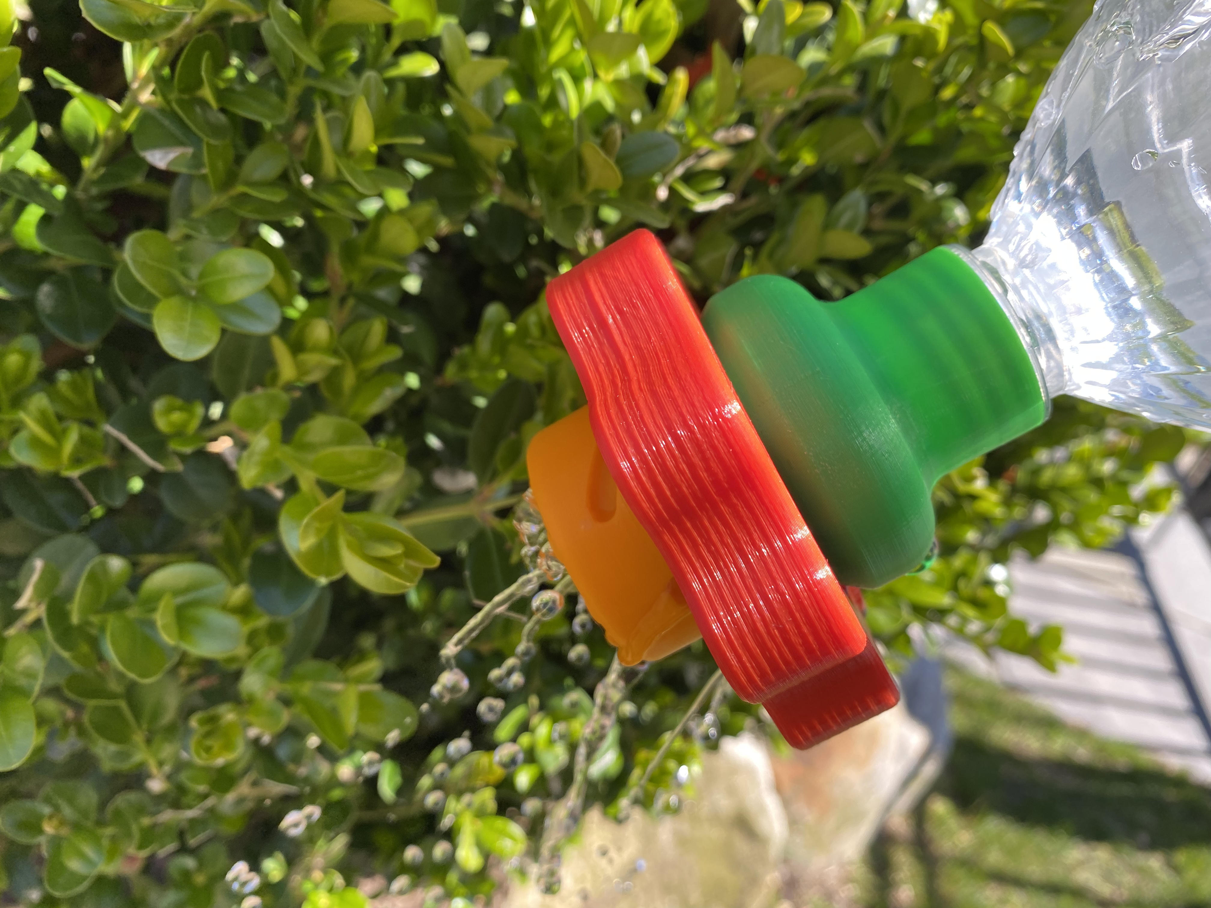
Adjustable Flow Watering Bottle
prusaprinters
<h3>Intro</h3><p>This is a watering head for a water bottle that allows you to adjust the flow of water that comes out. It prints in 3 parts, and is adjusted by turning the red knob. It should work with most standard water bottles sold in the US, although it might be a bit of a tight fit.</p><h3>Printing</h3><p>I sliced this using mostly default “optimal” settings in PrusaSlicer for my Ender 3, and was able to get away with the overhangs and bridges in most places. 10% Infill is fine, as this takes basically no stress whatsoever.</p><h5>Watering Bottle_Connector.stl</h5><p>This is the only file you should need supports for, and they are minimal at that. Using the paint supports tool in PrusaSlicer, put supports around the square cutout that you can see by looking through the bottom of the model. Look at the image below for reference.</p><figure class="image image-style-align-center image_resized" style="width:75%;"><img src="https://media.prusaprinters.org/media/prints/64845/rich_content/76bd9cdc-c346-4695-9c98-0de1e359c4bb/screen-shot-2021-04-26-at-42620-pm.png#%7B%22uuid%22%3A%2225211c01-d6e8-4406-ace7-a24f8bf9dc23%22%2C%22w%22%3A2486%2C%22h%22%3A1712%7D"></figure><h5>Watering Bottle_Body.stl</h5><p>This file should just print as is, with the flat part facing down on the build plate. I dislike sanding so the part doesn't have the best tolerances, but if you are willing to spend the time doing so then feel free to scale it up by a percent or so. Print without supports.</p><h5>Watering Bottle_Handle.stl</h5><p>Not much to say here. Print with the side that has the smaller hole down, without supports.</p><h3>Post Processing</h3><p>Remove the supports from the connector piece, and if possible use some sort of rubber seal/gasket/foam tape/du(ck/ct) tape inside with a hole cut out to create a seal with the holes. (refer to below picture.) You basically just want to prevent any water from going out of any hole other than the center hole when the thing is in the retracted position.</p><figure class="image image_resized" style="width:75%;"><img src="https://media.prusaprinters.org/media/prints/64845/rich_content/62865fac-aea3-45b8-87bc-ba3bdd6d465e/image-2.jpeg#%7B%22uuid%22%3A%22f04747dc-7140-41c5-bfc5-68c03c50919f%22%2C%22w%22%3A1440%2C%22h%22%3A1920%7D"></figure><p>Next step is to place the larger end of the (in my case green) connector piece into the larger hole of the (in my case red) handle piece. If needed, rotate it around so that the notches are able to bring the green piece under the pegs in the red one and are locked into place.</p><figure class="image image_resized" style="width:75%;"><img src="https://media.prusaprinters.org/media/prints/64845/rich_content/791fd4e5-68e3-47f9-8e9e-66926b090c85/image-3.jpeg#%7B%22uuid%22%3A%22aec96cce-9173-45cd-a3fc-38cd2f0f4058%22%2C%22w%22%3A1440%2C%22h%22%3A1920%7D"></figure><p>Now, turning the whole thing over, rotate the red handle so that the pegs on the handle are roughly perpendicular to the pegs on the green connector piece. </p><figure class="image image_resized" style="width:75%;"><img src="https://media.prusaprinters.org/media/prints/64845/rich_content/7c461c40-9ece-4599-999c-2d23053c4a88/image-4.jpeg#%7B%22uuid%22%3A%2278ea1675-290b-4ff1-801e-771ca8e8c40d%22%2C%22w%22%3A1440%2C%22h%22%3A1920%7D"></figure><p>Now, looking at the remain body/sprinkler piece (in my case yellow), place it into the hole in the red handle piece so that the smaller channels in the yellow part (that are connected to the longer curves) slot into the red pegs and the yellow part is able to rest on the green pegs underneath.</p><figure class="image"><img src="https://media.prusaprinters.org/media/prints/64845/rich_content/284bd73b-eb9c-4c19-a087-1a0b1708f60c/image-5.jpeg#%7B%22uuid%22%3A%22ab281b6f-1bfd-4d0c-968b-358768109ba4%22%2C%22w%22%3A1440%2C%22h%22%3A1920%7D"></figure><p>Rotate the yellow part counter-clockwise until it falls into place</p><figure class="image"><img src="https://media.prusaprinters.org/media/prints/64845/rich_content/41e095dd-42ce-444c-92a7-40a8961beeef/image-6.jpeg#%7B%22uuid%22%3A%221263e855-6b06-440c-a9ec-294ef5fb6264%22%2C%22w%22%3A1440%2C%22h%22%3A1920%7D"></figure><p>Now all that's left to do is to try and slot the red pegs through the yellow piece's channels so that the red pegs are in the long channel that is at a roughly 45° angle. The pattern to put it in the correct location is to turn the yellow part first all the way to the right, lift it as far as it will go, and then turn it right again. Once turning the red knob results in the yellow part going up and down, you'll be all set! Simply screw it onto a filled water bottle and go to town. If you are having trouble getting the water to come out, punch a hole in the bottle to allow water in.</p>
With this file you will be able to print Adjustable Flow Watering Bottle with your 3D printer. Click on the button and save the file on your computer to work, edit or customize your design. You can also find more 3D designs for printers on Adjustable Flow Watering Bottle.
