AA battery dispenser and checker
prusaprinters
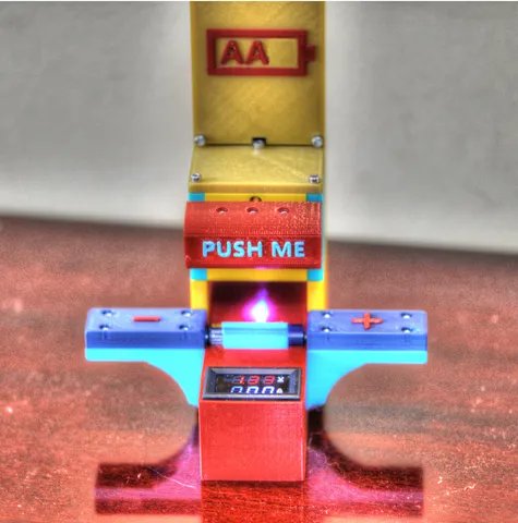
This is a AA battery dispenser that dispenses batteries upon pressing a button and automatically measures the battery and lights a led if the battery is of any good. Print instructionsWhat is it It's a battery dispenser that measures the voltage of the AA batteries upon pressing the dispose button. It has a capacity of 10 AA batteries and it works flawlessly, I have not seen a single battery failure when pressing the button. The principle is simple: upon pressing the button a battery will drop and travel to "a special place" where it will meet 4 magnets that will force the battery in a specific position. Two of that magnets will make electrical contact and activate an IR led, the IR led will activate a phototransistor, and the phototransistor will activate a transistor and the transistor will activate a led and a volt amper meter that will measure the battery voltage. When the battery is removed the whole circuit closes automatically. You can find a video here: https://youtu.be/W0bwB60_FJU Tools you need tweezers soft hammer (a hammer that is not made out of metal, maybe a wood hammer - I used a hammer with a plastic head, you can see an image in step 1) pliers to cut wires striping pliers screwdriver soldering iron 3D printer a measuring device (for continuity...) Materials you need 3mm screws, flat, round head of the following lengths 8mm, 10mm, 20mm. The head of these screws is 3mm in length and 6mm in diameter. A 3D printer PETG filament, some parts will not work well with PLA, don't even try. 4 neodymium magnets 3mm in height, 3mm radius. Electronic components: a) 1 x IR led b) 1 x phototransistor c) 1 x 10 Ohm resistor d) 1 x 20 KOhm resistor c) 1 x 470 Ohm resistor d) 1 x 5mm LED e) 1 x 2N2222A transistor f) 10 x AA batteries g) 1 x 9V battery h) 1 x 9V battery contact i) a volt amperemeter like this: https://www.aliexpress.com/item/4000035398329.html?spm=a2g0o.productlist.0.0.450a155f63nuw6&algo_pvid=cd1358b0-1a28-4754-80f2-c9e486513483&algo_expid=cd1358b0-1a28-4754-80f2-c9e486513483-4&btsid=0bb0624016113185477647942ec5e3&ws_ab_test=searchweb0_0,searchweb201602_,searchweb201603_ j) electrical wires - I used wire from a UTP cable, wire with a sing cable inside to be more rigid as you will need to push the wire through a small hole. k) 3 small extension springs 5mm diameter, 1cm length Print the pieces Print all pieces according to the GCodes I published using PETG filament. If you use the STLs you must add supports only to the battery_remover piece and you should add a color change to the face.stl, button.stl, lateral_module_upper_part_plus.stl, and lateral_module_upper_part_minus.stl Mount the magnets For this, you will use a hammer, a long bolt with a flat head, 2 bolts(3 mm in diameter, 10 mm in length), and the pieces named battery_remover, ir_led_and_phototransistor_cylinder, and screw_and_magnet_socket. Insert the screw in the screw_and_magnet_socket as in the image. Insert the rest of the bolt in the ir_led_and_phototransistor_cylinder. You will just use for the moment the ir_led_and_phototransistor_cylinder, this is not the final destination. Place the screw_and_magnet_socket with the bolt and ir_led_and_phototransistor_cylinder on a soft surface, I used a hexagonal dumbbell filled with sand and hammer the magnets in. Check that there is continuity between the magnet and the screw. You may need to extract and reinsert the magnet a few times as some residue of plastic may get stuck between the magnet and the screw head. Use the long bolt and put the magnet on the head, place the battery_remover on the soft surface, and hammer on the long bolt to fit the magnets in. Mount all the pieces Mount all pieces as in the blender file. Place extension springs of 5 mm diameter, 10 mm length between the pieces contact_hook and screw_and_magnet_socket. You can find these names in the blender file, in the group named "3D printer" Use M3x10 screws to fix the "lateral module lower part with arc" with the "lateral module upper minus" and "lateral module upper plus" Use 3xM3x18 and 1xM3x10 with a nut to fix the "lateral module lower part with arc" to the "Base for volt-ampere meter" Screw 2xM3x18 in the places where the "Battery remover" must fit, unscrew them in such a way that the "Battery remover" will snap in perfectly. Use 6xM3x18 to fix the "backbone" to the "Base for volt-ampere meter". Use the last spring to attach the "separator body" to the "separator upper slider". Then you will mount the pieces in the Gcode named separator_full_0.2mm_PETG_MK3S_8h56m.gcode you must mount them in such a way that the "separator upper slider" is exactly at the border of the "separator body" and the "separator lower slider" is out by just a few millimeters to stop the battery from escaping. Mount a led on the bottom of the, attach the wires and make the wires exit through the special hole. Wires will go on through the backbone and "base volt-ampere meter". Electrical part Use an IR led and a phototransistor of 5mm diameter, insert them both in the ir_led_and_phototransistor_cylinder. Solder all the electronic pieces as shown in the circuit. I used no PCB, I just soldered the pieces, isolated them, and folded them into the "Base for volt-ampere meter". Calibration Use the two "Bolt" objects to set the right spring tension. Calibrate the volt-ampere meter according to the manufacturer's specifications. Improvements for the future The backbone should have a special extrusion that will not permit for the batteries to be inserted in reversed mode (plus to minus) The voltmeter could be placed in an inclined position instead of the horizontal one. The electrical part needs a PCB. Some kind of a cover is needed to stop the batteries from exiting the device when upside down. I have observed that batteries that are bad and a little bit inflated do not descend well from the device so the base and the backbone should be 1-2mm wider. Final words I'm not an electrician, the electrical part may be improved by a specialist. Use it as it is at your own risk. The 3 unused holes in the backbone can be used for mounting the device on a wall. On the main image displayed on the project you can see a AAA on the object, this is a mistake that I rectified on the final print files, batteries are AA. The voltmeter needs to be calibrated, I have not followed the calibration procedure. You may like You may like this project I made on my Prusa: https://www.instructables.com/Electric-Puzzle-Game/ Changelog 24.01.2020 The contact magnets have been placed 1mm back(further from the battery). Bolt holes for the lateral modules have been placed in such a way that they will not interfere with any other holes. The two lateral screws have now a straight shaft, not a hexagonal one. The hexagon is easily broken. The volt-ampere meter base has now a cover so you can easily access the inside of the box. The lateral modules have been modified so that the screw cannot be completely unscrewed from the "lateral module cylindrical slider". All stl's are in the correct position for print.
With this file you will be able to print AA battery dispenser and checker with your 3D printer. Click on the button and save the file on your computer to work, edit or customize your design. You can also find more 3D designs for printers on AA battery dispenser and checker.