A better steering tie rod for RC cars
prusaprinters
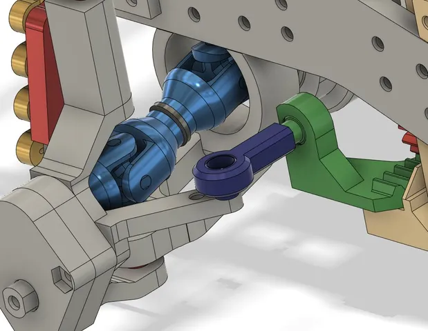
My former tie rod design also had 2 ball joints, but due to their vertical orientation (the screw tube orientation), movement was limited as the screw tube would come in the way of the joint at a relatively small angle which lead to flexing of the drag link in case of too much suspension travel.This time, looking at how real life tie rods are designed, I tried to give as much movement as possible to the inner tie rod. I also eliminated the top part of the screw tube and reduced its external diameter to 2 perimeters. (I use M3 screws). Indeed, the inner tie rod pivots a lot vertically (with suspension) whereas the outer rod mostly pivots horizontally with the wheel turns…I also made it adjustable (16 mm M3 screw) … this might be an overkill because due to all the printing tolerances steering is pretty wobbly anyways. But it might be useful to adjust for bump steer (which is a compromise, because there will always be some bump steer happening). I would adjust the tie rod length so that there is no toe in or out with the full load of the car (battery and body included). The inner rod is supposed to be mounted on the drag link and the outer rod to the wheel knuckle.The cover picture shows the tie rod in my UNIMOG design; the inner tie rod is part of the drag link. I've uploaded the independent version that is supposed to be screwed to some other part… As a matter of fact it is used on rear wheels assemblies. This is a print in place design. The inner rod ball joint is not free when it comes out of print, which allows you to drive the screw more easily into the outer tie rod. You can then use the outer rod movement to free the ball joint.
With this file you will be able to print A better steering tie rod for RC cars with your 3D printer. Click on the button and save the file on your computer to work, edit or customize your design. You can also find more 3D designs for printers on A better steering tie rod for RC cars.