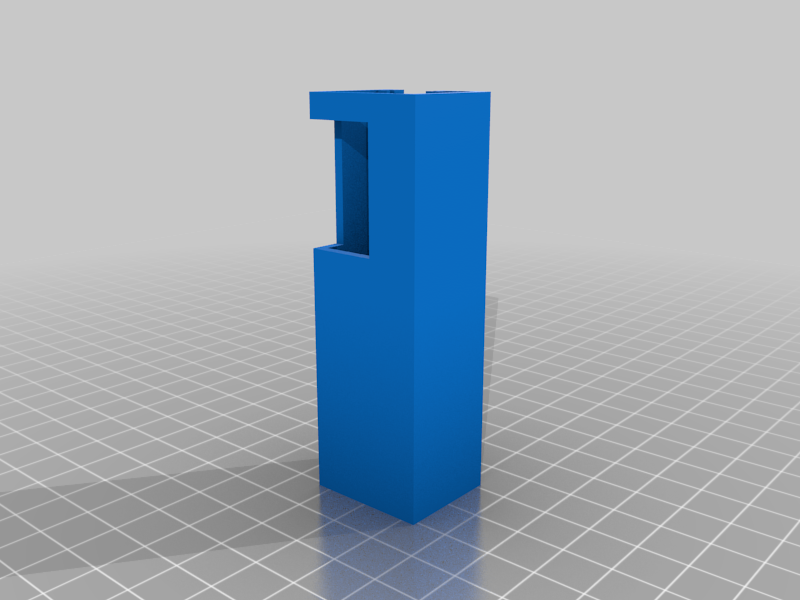
9 pin ( Atari, Amiga C64 and others) Joystick tester
thingiverse
Joystick tester for 9 pin joystick, including cable. Tester has 9 pin male connector for joystick connection. Pinout is as follows: Top row: 1-UP 2-DOWN 3-LEFT 4-RIGHT 5-N/A Bottom row: 6-FIRE 7-5V(powers autofire) 8-GND 9-second FIRE, used for Amiga computers, for example. Tester features 6 green LEDs (UP,DOWN,LEFT,RIGHT,FIRE,second FIRE), flashing when activated on joystick. Red LED serves for the purpose of testing ground wire. Tester also features pins to connect hook test probes for purpose of wire tests by connecting these inside of joystick. Longer row of pins is grounded. Shorter row of pins is connected to 5V ( for purpose of testing ground cable). Principe of operation: 9-pin joysticks grounds wires of directions and fire buttons to ground. This is used by tester for flashing LEDs accordingly. LEDs needs to flash according to joystick's directions and fire buttons. Circuit requires 5V power, which can be realized easily by power bank, for example. Hook probes can be also used for testing of joystick's functions, these needs to be connected on all wires with exception of 5V and GND. All GREEN LEDs should be then flashing, and wire can be stressed by twirling of wire, per Zdenek's wish. GND can be tested by connecting of 5V to GND wire, RED LED should be flashing. 5V and autofire can be tested by turning autofire on, making LED indicating FIRE lighting less that before. Hooks also serves for testing of tester itself by connecting these directly to its connector's pins. I've realized prototype with an universal PCB 2x8 cm and put it in 3D printed enclosure of my own design. I've used an USB connector for powering circuit.
With this file you will be able to print 9 pin ( Atari, Amiga C64 and others) Joystick tester with your 3D printer. Click on the button and save the file on your computer to work, edit or customize your design. You can also find more 3D designs for printers on 9 pin ( Atari, Amiga C64 and others) Joystick tester.
