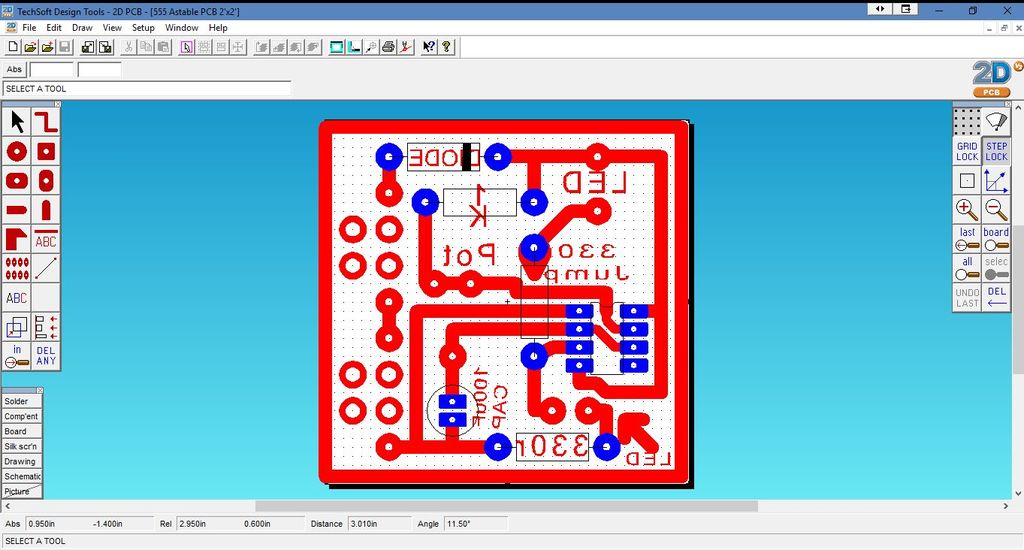
555 Astable Circuit Diagram and PCB Layout - Techsoft 2D PCB
thingiverse
Astable Multivibrator Circuit Diagram and PCB Layout - Techsoft 2D PCB Design The astable multivibrator circuit is a fundamental electronic design that produces a square wave output. The circuit consists of two cross-coupled transistors, a resistor, capacitor network, and an external power source. To create the astable multivibrator circuit diagram and PCB layout, we will use Techsoft 2D PCB design software. This software allows us to create a professional-looking PCB layout with ease. First, let's create the schematic diagram of the astable multivibrator circuit. We will start by creating two transistors, Q1 and Q2, connected in a cross-coupled configuration. The collector-emitter path of each transistor is connected to a capacitor, C1 and C2 respectively. Next, we will add the resistor network to the circuit diagram. The resistors, R1 and R2, are connected between the base of each transistor and ground. We will also add the power source to the circuit diagram, connecting it to the collector-emitter path of each transistor. Now that we have created the schematic diagram of the astable multivibrator circuit, let's move on to creating the PCB layout. In Techsoft 2D PCB design software, we can create a new project and import our schematic diagram. The next step is to create the PCB layout by placing components on the board and connecting them according to the schematic diagram. We will start by placing the transistors Q1 and Q2 on the board, followed by the capacitors C1 and C2. Once we have placed all the components on the board, we can connect them using copper wires. The resistors R1 and R2 are connected between the base of each transistor and ground, while the power source is connected to the collector-emitter path of each transistor. Finally, let's add a square wave output capacitor, C3, to the circuit diagram. This will allow us to observe the square wave output produced by the astable multivibrator circuit. With our PCB layout complete, we can now generate a fabrication-ready Gerber file using Techsoft 2D PCB design software. This file can be sent directly to a PCB manufacturing service for production. In conclusion, creating an astable multivibrator circuit diagram and PCB layout using Techsoft 2D PCB design software is a straightforward process that requires careful attention to detail. By following these steps, you can create a professional-looking PCB layout with ease.
With this file you will be able to print 555 Astable Circuit Diagram and PCB Layout - Techsoft 2D PCB with your 3D printer. Click on the button and save the file on your computer to work, edit or customize your design. You can also find more 3D designs for printers on 555 Astable Circuit Diagram and PCB Layout - Techsoft 2D PCB.
