3D UnderClippy v2 - Filament Cutter for 3DChameleon
prusaprinters
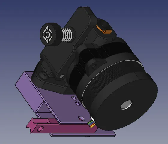
Update:4/13/2024 - v2 Released!This revision improves slicing by adding 1mm of travel past the filament. The previous design did not account for wear on the blade and failed as a result after a short time. The new design also increases the blade slot size to allow easier insertion into the plunger. The tight version is still available for well tuned printers. There are a few revisions in the instructions below.Note: I have determined that the grub screw is just insufficient to hold the blade securely. I found it best to apply a little superglue into the grub hole before inserting it. This make adjusting and replacing the blade impossible. A new plunger would have to be printed for a new blade.3D UnderClippy:This design is loosely based on the open source 3D Clippy. It differs in that it's installed under the extruder adding only 10mm to the filament path. So far, I've designed bodies for use with the Orbiter and the various Sailfin extruders. I'll add more if requested.The 3D UnderClippy can be installed in any orientation under the Extruder to trigger it from front or rear and left or right. In my case I only have the rear bars to trigger against. If you've got an enclosure or frame, it might be preferable to mount it with the trigger on the front.Additional Hardware Required:0.5mmx3mmx10mm 304 Stainless Steel Compression Springs (2)M2-0.40x3mm 12.9 Hex Socket Set Cup Point Grub Screw (1)9mm Wide Snap-Off Blades from box cutter (1)M3-12mm bolt for attaching the lever.2 M3 bolts 10mm longer than what is currently used for the extruder.A 0.9mm Allen Wrench for the grub screw. Note: I found this in a cheap. multi-bit screw driver kit from the local hardware store.A 2mm Allen Wrench, preferably with a ball end.Note: These links are only suggested sources. The grub screw was exceptionally hard to find and I had to buy 50 of them (cheap though…).Printing Instructions:Print your desired body along with the plunger and lever. Use Standard PLA at 40% infill or more. Do not use Velvet type PLA since it expands when printed and will interfere with critical tolerances. All parts will print without supports or brims positioned with the flat side down and the opening of the body up (See attached photo). It's important that your printer is tuned as well as possible.Assembly Instructions:After printing, use a 2mm Allen Wrench or Drill Bit to expand the filament hole in the Body. Filament should pass through the hole without obstruction.Break the blade between 12 to 15cm from the point so that the end away from the blade is as flat as practical. I did this using two long-nosed pliers, holding the blade securely at the position I held it with one pliers and then using the other pliers to bend the blade and break it. It may take couple of tries, but there's plenty of extra blades in the cutter.Slide the blade into the plunger so the tip is about 6.5mm from the end. Depending on how well tuned your printer is, It may help to insert the blade's sharp end into the plunger first to clean the slot. Then remove it and reinsert the blunt side in. Use the 0.9mm allen wrench to insert the grub screw into the side of the plunger to grip the blade. Not too tight, as you may need to adjust it later.Insert springs into the holes either side of the plunger cavity of the Body. I used a very small Phillips screwdriver to guide the springs into the holes.Position the Plunger into the Body with the grub screw oriented toward the adjustment holes on one side.Use the flat side of the Lever to press the Plunger past the tabs on the sides of the Body. The springs should fall into the holes of the Plunger.Note: I used a 1mm Allen wrench, between the springs and the Body to gently pry the Plunger out when needed.Determine the orientation you will need to install the body under your extruder. Determine which direction the lever will need to be positioned. The end of the Lever should be pointing toward the side of the printer that will trigger it.Insert the Lever, cam side toward the Plunger and insert the 12mm bolt from the side that will be upward, toward the extruder. Don't over tighten it as it will stay where it is and the lever needs to be loose.Tune the Blade:Check that the blade completely clears the filament path. If not, loosen the grub screw slightly through the adjustment hole and gradually insert a 2mm Allen Wrench into the filament path. Wiggle it around to move the bade out of the filament path. Once complete, tighten the grub screw. Not too tight, as we don't want to strip the threads in the Plunger.Press the Lever to lower the Plunger. Hold the 3D UnderClippy in front of a bright light to verify that the blade completely covers the filament path. If not, loosen the grub screw slightly. Press the Lever to lower the Plunger. Press the 2mm Allen wrench firmly against the blade and release the lever just a tiny bit to move the blade away from the Plunger. Remove the Allen wrench and check it again. Repeat as necessary. Tighten the grub screw. Again, not too tight! Note: It may be easier to remove the plunger to work the blade out a bit. The ideal position is 6.6mm from the plunger end.If you needed to adjust to blade in the last step, repeat the previous step to verify that the blade clears the filament port. There is just enough travel that the blade will adjust properly.Once complete, I recommend removing the plunger and applying a little superglue under the grub screw. This will prevent it from working loose in the future. You will have to print another plunger when the blade needs to be replaced.Install the 3D UnderClippy:Measure a piece of Bowden tubbing to fit all the way into your hot-end. Add 1mm to that length and cut it. Do the same with the Extruder exit port.Place the hot-end's Bowden tube into the hot end and press the 3D UnderClippy firmly into position. Place the Bowden tube into the Extruder and place it on top of the 3D UnderClippy. Using the longer M3 bolts, attach your Extruder through the 3D UnderClippy and into your original mount.Not Quite Done!At this point, you should be ready to design a Trigger for your printer. I've included a number of sample triggers ranging from 0-45mm from the base of the lever's insertion slot. You may need to modify these triggers to account for the distance between the gantry supports and the 3D UnderClippy's lever. Note that I've also included a Lever Cap in STEP, STL and SCAD as a basis for building your Trigger on. The Key in the Lever Cap's end is only on one side to allow printing with the key on the bottom. Use an M3-12mm bolt to secure the Trigger to the Lever.Note that the Trigger will fold around and behind the 3D UnderClippy to disable it when not needed.Let me know if you think of any improvements to this design! Feel free to share this and remix to your heart's content!GCode Samples:Include the code in the appropriate area of your Tool change G-code (PrusaSlicer) or Filament Start G-Code (OrchaSlicer).Trigger on right at X460:; go to holding position to unload the stock extruder G0 X230 Y254 F2000 ; <<----- EDIT THIS LINE TO SET THE INITIAL LOCATION OF THE BUTTON & CUTTER ; if this is the first load, then don't unload G91 ; move to relative mode M83 ; load extruder #{next_extruder} M117 Loading Tool T{next_extruder} {if previous_extruder>-1}; Not First Load ; back out the filament for cutting G0 E5 F1500; spit a little filament before retracting. G0 E-55 F1500 ; retract to 5-10mm before cutter, adjust this to tune waste. ;******* 3D UnderClippy Code ******** M906 X1060 ; Boost Stepper Current ; cut off filament tip G0 X30 F5000 ; Cut the filament quickly G0 X-30 F5000 ; Move X back to position M906 X580 ; Restore Stepper Current ; ******* End UnderClippy Code ; we skipped to here if it was extruder -1 {endif} {if previous_extruder>-1}; If NOT first extruder ; retract it back out of the extruder G92 E0 G0 E10 F1500; push filament past cutter G0 E-60 F1500; retract again 5mm beyond extruder's gear G92 E0Trigger on left at X0:When using this mode, prevent any printing below X30 as it will restrict filament movement. Be sure to also move the prime line out of this area!; go to holding position to unload the stock extruder G0 X30 Y254 F2000 ; <<----- EDIT THIS LINE TO SET THE INITIAL LOCATION OF THE BUTTON & CUTTER ; if this is the first load, then don't unload G91 ; move to relative mode M83 ; load extruder #{next_extruder} M117 Loading Tool T{next_extruder} {if previous_extruder>-1}; Not First Load ; back out the filament for cutting G0 E5 F1500; spit a little filament before retracting. G0 E-55 F1500 ; retract to 5-10mm before cutter, adjust this to tune waste. ;******* 3D UnderClippy Code ******** M906 X1060 ; Boost Stepper Current ; cut off filament tip G0 X-30 F5000 ; Cut the filament quickly G0 X30 F5000 ; Move X back to position M906 X580 ; Restore Stepper Current ; ******* End UnderClippy Code ; we skipped to here if it was extruder -1 {endif} {if previous_extruder>-1}; If NOT first extruder ; retract it back out of the extruder G92 E0 G0 E10 F1500; push filament past cutter G0 E-60 F1500; retract again 5mm beyond extruder's gear G92 E0
With this file you will be able to print 3D UnderClippy v2 - Filament Cutter for 3DChameleon with your 3D printer. Click on the button and save the file on your computer to work, edit or customize your design. You can also find more 3D designs for printers on 3D UnderClippy v2 - Filament Cutter for 3DChameleon.