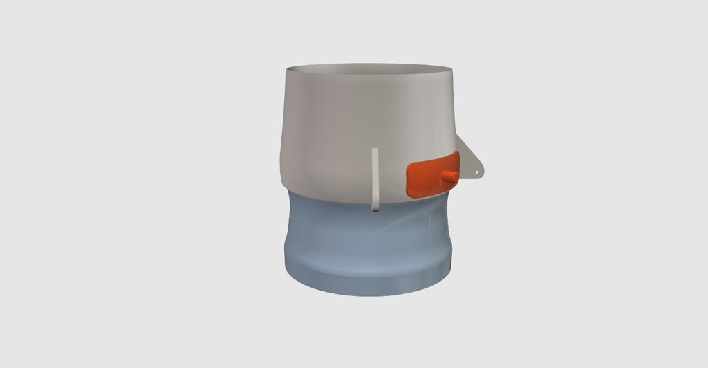
360° Thrust vectoring (TV) unit
prusaprinters
<p>A 360° thrust vectoring unit for 70mm EDF's.</p> <p>The unit should be scalable as it originates from a smaller design, plus you have the ability to tighten the nozzle via a screw helping you with tolerances.</p> <p><strong>The ball joint has an inner diameter of 62.8 mm on the thrust tube side.</strong></p> <p>You can mount the unit normal (one servo for horizontal/pitch and the other servo for yaw movement) or tilted by 45° to one side were both servos are mixed together to achieve pitch and yaw movement (a simple elevon or delta mixer)</p> <p>Required parts:</p> <ul> <li>2x push rods with z-bends or ballheads</li> <li>2x 9g servos</li> <li>1x ~2,5 x 8 mm wood screw <h3>Print Settings</h3> </li> </ul> <p><strong>Rafts:</strong></p> <p>Doesn't Matter</p> <p><p class="detail-setting supports"><strong>Supports: </strong> <div><p>No</p></div><strong>Resolution:</strong></p> <p>0.2 mm</p> <p><p class="detail-setting infill"><strong>Infill: </strong> <div><p>20-30%</p></div></p> <p><strong>Notes:</strong></p> <p>Print with two wall lines (0.8mm), for rigidity and for a smoother surface as the infill doesn't show through.</p> <p>Print the parts upright without support (only the pin mount could need some support).</p> <p>A finer resolution could save you some time sanding, but i only printed at .2 mm</p> <h3> Post-Printing</h3> <p><strong>Sanding!</strong></p> <p>You need to sand down the contacting surfaces both on the outside of the ball joint as well as on the inside of the nozzle to get rid of any layer lines and to make the assembly easy to move.</p> <p>I started with 120 grit and worked my up to ~ 600 grit in a whole of 4 steps.</p> <p>After I was done sanding I sprayed some PTFE dry lube onto a paper towel and rubbed over all the surfaces of the nozzle and ball joint i just sanded down to minimize friction/stiction, any other lubricant like simple oil should do.</p> <p><strong>Assembly</strong></p> <p>1: Find a fitting screw for the blocks on the side of the nozzle and drill out the holes if needed (but dont screw it in yet !)</p> <p>2: Glue the pin mount to the nozzle, so it is in the center of a axis movement (e.g. yaw axis) with CA or any other glue that works good with your filament. The pin (orange) is supposed to be guided by a small piece with a slot in it (turquoise) to secure the nozzle from rotating.</p> <p>3: Now carefully push the nozzle on to the ball joint until it sits in place, now screw in the screw you just picked and tighten it until you can still move the assembly easily and there is no play.<br/> <strong> if you are afraid the nozzle is to tight to fit on the ball joint just slice in a small slot with a hot knive on the opposite side of the screw.</strong></p> <p>4: Mount the push rods to the two horns on the nozzle either via z-bend or some ballheads.</p> <p>Now the whole Unit only needs to be mounted to your thrust tube and two servos have to be installed and you're done!</p> <p><strong>The unit works without the pin and I successfully landed several flights this way but now I mount it, and so should you, for the added level of security without adding any real weight!</strong></p> </p></p> Category: R/C Vehicles
With this file you will be able to print 360° Thrust vectoring (TV) unit with your 3D printer. Click on the button and save the file on your computer to work, edit or customize your design. You can also find more 3D designs for printers on 360° Thrust vectoring (TV) unit.
