3018 DIY CNC: T8 Leadscrew / Anti Backlash / Spring-loaded nut Spindle Head
thingiverse
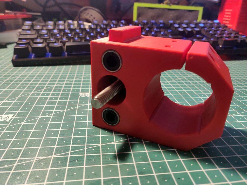
In addition to my revision of the drive transmission of the Y axis (see [here](https://www.thingiverse.com/thing:4202480) and [there](https://www.thingiverse.com/thing:4118050)), I have also revised the holder for the spindle motor so that backlash-free T8 spindles can be used with it without any problems. In addition, there is a cam for triggering optional limit switches on the Z axis. The limit switches can be attached to the right side of the X-axis part of the holder. Instructions from version 1.0.4 The fumbling with M3 nuts annoyed me. In addition, the spring may be blocked by these cheap, ragged nuts, but their full functionality depends on the ease of movement of the spring. Therefore, from version 1.0.4, I did not attach the spindle nut with M3 screws and nuts. Instead, the nut is now attached with 4 M3x15mm screws. If this is too unsafe for you: Put a drop of superglue in the M3 hole, this will keep the M3 screw bombproof. Please check beforehand whether the M3 thread also fits well. So when the spindle nut is where it should be, you put the spring on the nut from the other side, push the lock nut with two webs into the recess in the spindle nut and then turn the TR 8 spindle through both nuts. If it runs smoothly and without great resistance and the lock nut does not turn, you are almost there: You have successfully assembled the thing. Some of the parts required to replicate this thing include: 1 x 100mm TR8 Rod and anti-backlash leadscrew with spring 4 x M3x20mm Head Socket Head Cap Screws 2 x M3x25mm Head Socket Head Cap Screws 6 x M3 Nuts 1 pair of tweezers to place the fiddly M3 nuts, if you have sausage fingers like me. Optional: Some Makerbot Endswitches. For assembly suggestion see last photo. To do List: Extension for focal point laser measuring system with line laser History: 2020/02/05: Internal Version 1.0.1 with first Tests 2020/03/01: Tolerance for IGUS bearings slightly increased after printer recalibration. Tolerance for IGUS bearings slightly increased after printer recalibration. The bearings were too tight at a colleague's printer. 2020/03/05: Public Version 1.0.3. Some minor changes to make screwing the spindle nut easier. This is the final version in this branch of development. 2020/03/08: New photo from version 1.0.3 placed in 1st place. 2020/03/09: Version 1.0.4b. Simplified assembly of the lock nut: No more M3 nuts required. Threads for fastening the spindle nut with 4 M3x15mm cylinder head screws are also printed. 2020/03/09: Version 1.0.4a: Version without a cam for triggering optional limit switches. 2020/03/10: Smaller dimensional changes: Distance between spindle bore and Z slide increased. 2020//03/14: Version 1.0.41a: Smaller dimensional changes: Some spindle nuts apparently come with larger springs. So I expanded the 13mm hole to 13.5mm. More makes no sense, as otherwise the M3 screws for securing the nut will no longer find sufficient hold. Some of the links are suggestions for parts to replicate this thing and affiliate. If you buy something, I get a small commission. The price you pay is the same. Thank you very much.
With this file you will be able to print 3018 DIY CNC: T8 Leadscrew / Anti Backlash / Spring-loaded nut Spindle Head with your 3D printer. Click on the button and save the file on your computer to work, edit or customize your design. You can also find more 3D designs for printers on 3018 DIY CNC: T8 Leadscrew / Anti Backlash / Spring-loaded nut Spindle Head.