2" Rack & Pinion Focuser for Hadley 114/900
prusaprinters
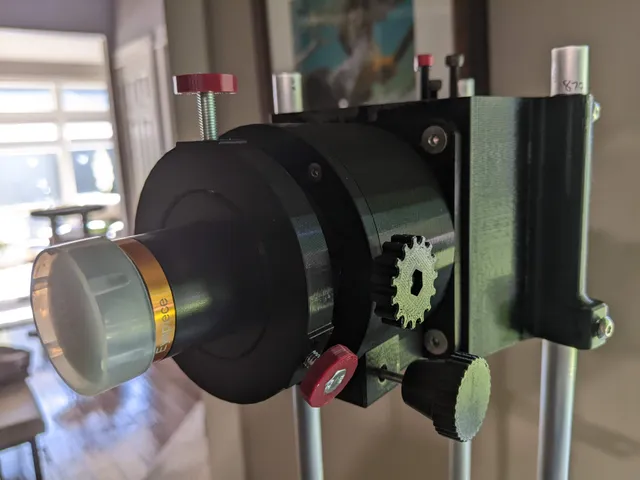
This isn't really a remix so I didn't add that info, but I want full credit to go to Maff for his supremely cool telescope model that I am enjoying the crap out of, and for inspiring me to try something new (astronomy) and continue refining the design.For a few reasons, I chose to design and build a rack-style focuser to replace the helical version on the original model. There are several Crayford style focusers out there in the 3DP world (and they may be better than this) but I felt better about designing this style, so that's what I did.Rather than having a simple "tube inside a tube" design like the typical crappy rack focuser, I chose to have the drawtube slide on 5mm rods with linear bearings, much like the system the printers use. I figured that way I could get a smooth sliding assembly that would be somewhat less reliant on the quality of the gearing, since that is always challenging with prints.WHY 2"?The original focuser provided with Maff's model is for 1.25" lenses, but I chose to make this focuser accept 2" lenses (as well as 1.25"). Why? Well, there are a lot of really technical issues you can read about for yourself and much back-and-forth about which is best, but at the end of the day I figured if I was going to take the time to design an assembly, it only made sense to have it accept the larger eyepieces in case I find one I want for whatever reason. A simple bushing (included) is all you need to stick with 1.25" so no blood no foul.PS - I can confirm that it works REALLY well, with a wider unobstructed view than the other one. The helical focuser seems to chop the side of the field of view somewhat, but this 2" tube (and redesigned UTA I suppose) does not.A NOTE REGARDING MY APPROACH TO HOLES:Unless I say so otherwise below, I kept all of the holes at ZERO tolerance. Meaning, if the hole is going to get a 3mm rod I designed it at 3mm exactly, knowing full well that the printer would squish this a bit and the hole would need to be reamed a bit. This is intentional, so please don't message me telling Rod A doesn't fit in Hole B. Since this was intended to be a close tolerance assembly overall, I wanted to be able to make decisions along the way regarding how much to loosen up any given hole/part/etc. That allowed me to keep things tight where I wanted and give a little slop where the design benefits from that. You can always drill some out, but it's damn tough to add material back in without printing everything 10 times.I'll tell you what I did and where in each section below.UPPER TUBE ASSEMBLY:At first, it was my intention to build the focuser to mate up with the UTA from the original design. After much tinkering it became obvious that was not the best path, so I reworked the UTA and included that file. Part of the reason behind the rework of the UTA is to keep the light path in roughly the same spot as the original design. I won't go into all the reasons why; you'll just have to trust me that meandering the focus point in and out (by adding/subtracting focuser height) creates lots of optical challenges and performance changes. So, if it aint broke….You will need to add supports to the 2" hole in the face (or just use the 3MF file).BEARINGS:The linear bearings I used are an LM5UU 5mm bore, 10mm OD, 15mm length, linked below. They PRESS FIT into the Lower Draw Tube Half, pretty obviously where (no hole reaming please). There are three of them. The rods are 5mm (I used solid stainless steel) and they are cut to 51mm. Dress the ends so they enter the bearings with screwing anything up.A note on the rods: (not gonna lie to you, this part gets a little fidgety). The holes in the Base and the Cap that receive the rods should be loosened up a little bit. You can actually drill out the holes a tiny bit, or do what I did and grind a small shoulder on to each ends of the rods, leaving the holes in the plastic alone. The issue here is that the linear bearings or frustratingly intolerant of even the slightest bit of off-axis with the rods. To provide enough wiggle to make the bearings happy, I tweaked the rods as noted above. We're talking about 0.10mm taken off the rod diameters maybe, not much. THE FOCUSING SHAFT:See the hardware section below for more info here (sizes and all that).There are two options here:Run a 3mm drill bit through a time or two so that the 3mm shaft rides firmly but still turns nicely. Call it good enough.I set the model up for (and inserted) brass sleeve bushings (see hardware list below and links). If you are going this route, you'll want to run a 5mm drill in to clean up the bushing holes as they dont press fit wall.GEARS:The rack gear is super glued into place. There is no up or down, either way is fine.The pinion gear has been discussed elsewhere at length (grub screw and all that).3D printed gears are what they are. You'll want to spend some time making the gears pretty, cleaning out the peaks and valleys, do a little chamfer job on the pinion….just generally clean them up and also loosen them up ever so slightly by doing so.When you assemble if they are still too tight for your liking, rinse and repeat until you like the feel.DRAWTUBE:This comes in two parts, an upper and a lower. There are 3 small holes in the mating faces that receive 10mm long pieces of 2mm rod used to align the pieces. Make sure and stick those in there, they are really helpful. The two halves are super glued together (see the Assebmly notes below please)ASSEMBLY:Assembly is very straight forward, with only ONE thing to watch out for.Make SURE that you put the Cap in between the two Draw Tube halves before you glue them together. Also make sure the Cap is right side up (ready to accept the countersunk screws and the bearing rods).Thats it, the rest is tinker toys.HARDWARE (THERE ARE S0ME WEIRD PIECES, SO BE ALERT):Hardware is all metric. The four bolts attaching the Base to the new UTA are M5x16 countersunk as the original model. If you go longer than 16mm the bolt will bottom out on the UTA, so don't do that. The four bolts attaching the Cap to the Base are M3 countersunk, and I think they're in the 15mm long range. There's some leeway there on length and the Cap is pretty thin so they don't need to be super long. You can ream out the holes in the cap with a 3mm drill bit if you like. The run-by holes under the threaded inserts are already designed larger.Take some measurements and make sure your threaded insert matched mine….meaning that it's top flange will settle into the provided void so the Cap flushes to the Base. I'm sure all threaded inserts are not identical.I used 3mm threaded inserts press fit into the base to receive the Cap screws. Don't ream out those holes, you want those to be tight.The three bolts that secure the lens are M5 and I set up the nut for square nuts. You can run a 5mm drill bit through those holes to make the bolts free spinning.The grub screw on the pinion gear….this is a little weird. I THINK it is a 4-32 (yes, imperial) but it was one I had on hand so not super sure. I had to grind some length off to make sure the grub screw didn't interact with the rack gear. Also, I did NOT tap those threads, I just let the grub screw tap it's own threads to keep it nice and tight. The two holes in the edges of the Cap are for “brake” screws so you can lock down the focus point when you want to so the focuser won't move, or “creep”. Those are set up for an M4 and are intentionally tight because I let the screws self-tap there as well. I provided thumb screw heads for the three lens screws (M5 hex head) and the two brake screws (M4 hex head)The focusing dial knobs are TIGHT, intentionally. I chose not to do a grub screw on those because if my assembly ended up so tight that I could spin the dials on the shaft I had failed. They press onto the focusing shaft 15mm each and I gently tapped them on with a hammer and wood block.The focusing shaft is a 3mm SS rod, 124mm long with a small flat grinded at the precise center to accept the pinion gear grub screw. Make sure the flat is just barely wide enough for the grub screw face and not so wide that it affects how the pinion gear lays on the shaft.Bushings on the focusing shaft are 3mm bore x 5mm OD x 5mm long. See link below. LINKS:Bushingsuxcell Sleeve Bearing 3mm Bore x 5mm OD x 5mm Length Plain Bearings Wrapped Oilless Bushings 10pcs: AmazonSmile: Industrial & ScientificLinear Bearingsuxcell LM5UU Linear Ball Bearings 5mm Bore 10mm OD 15mm Length for CNC Machine 3D Printer 4pcs: AmazonSmile: Industrial & ScientificLet me know if you have questions.
With this file you will be able to print 2" Rack & Pinion Focuser for Hadley 114/900 with your 3D printer. Click on the button and save the file on your computer to work, edit or customize your design. You can also find more 3D designs for printers on 2" Rack & Pinion Focuser for Hadley 114/900.