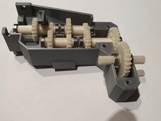
16 to 1 Gearbox for 2216 motor
prusaprinters
RC Car V2:This is a subset of my new RC car project that should allow to build (again) a fully functional RC 4-wheel drive car, but just a little bit more realistic or should I say to …"scale". I just started printing the first few sub-assemblies. I've already published a first version of my new differential and I'm going to update it soon once I print and debug it. You may also have seen my Michelin XZL tires.So, while I still have a lot to do on this project, I'm publishing the first “final” mechanical piece (the gearbox) that can be used for other designs or as is. It uses 6 steps to get 16 to 1 reduction. My intent is to provide a lot of torque while using one of my small 2216 motors.In this design I'm using the airplane propeller mode with the 2 aluminum parts that are provided with the motor. So, the stator is at the back (and I do not use the motor’s shaft) and the rotor in the front. The motor is mounted onto its support using the cross shaped aluminum part. The pinion mounts on the 2216 motor using the provided screw mount intended for a propeller that attaches to the rotor’s casing. You will need a M5 nylon insert nut and an 8 mm wrench to secure the pinion onto the motor shaft. (or not because the pinion is very tight - you might put some soap to help driving it up to the aluminum part)This design uses a set of M3 hex screws of different lengths and corresponding nuts. To assemble the motor to the motor support you will need 4x10mm screws + nuts (2 might do)For the gearbox housing assembly you need 2x12 mm + 5x20mm screws +nuts.The parts called GBH mount are glued to the main housing parts; you can use a small screw to hold everything in place until the glue has cured (and later remove it or … you can leave it there!)All the gears are helical gears as I made a compromise between easiness of assembly versus noise/torque transmission. Design wise, starting from a spur gear you need to compute the helix angle depending on the number of teeth knowing that the module for two connecting gears has to be the same (basically some high school trigonometry). I cheated at the end, so you have two weird 26 and 27 teeth gears on axle 5 and 6. Well that was the way to start from a centered pinion and finish on a centered output axle/shaft. I also adjusted the module on the two last gears, “pour tomber juste”.The pinion has 10 teeth, and each axle assembly features a set of 2 gears, one 20 teeth gear and one 12 teeth gear. Reduction is 0.6 per axle assembly (exception are axle 5 and 6). Axle 6 is the output axle, and it can be used on both sides (front and rear). All axles use two 11x7x3 ball bearings each. 11 is the external diameter and 7 is the inner diameter while 3 is the BB height (MR117-2RS). Gearbox assembly instructions:Assembly steps for each axle:Axles are embossed with their number; this number faces the motorPut a 20 teeth gear and push it until it stopsNext, put the axle's spacer (number also embossed on the spacer)Then, put a 12 teeth gearPut the small spacer (same part for all axles)Finally put the BB on each side of the axleAxle 5: the second gear is the 26 teeth gearAxle 6: there is only one gear (the 27 teeth one)To install the axle assemblies into the housing (i.e. GBH-R), you should start putting in axle 2 (it's a little tight but manageable); then axles 3, 4, 5, and 6. Axles positions are embossed on the housing. Then assemble GBH M (the triangle shaped part) to GBH R with a 12mm screw + nut. Then put in axle 1 and finish the gearbox assembly with GBH L and 5x20 mm screws + nuts. Final step: mount one 12 mm screw to assemble GBH M to GBH L.To assemble the gearbox to the motor support / motor/ pinion you need 2x12mm screw + nuts.I’m including some pictures as mounting aids.Printing tips:I retain my naming convention for parts:XXXnn-kk-nameXXX = sub assemblynn part number within this assemblykk number of instances needed in one single instance of the sub assemblyThe motor support is part of the chassis but I'm including it here for obvious reasons ;-)I used PLA for all parts. I read somewhere that we should use poly-carbonate for gears, but PLA seems to work just fine. PETG has a better resistance to heat but is more flexible which may not be ideal either… Well in my previous design I used PETG, and it also worked fine … I printed everything at 0.2; for gears and axles at 100% infill and 4 perimeters.
With this file you will be able to print 16 to 1 Gearbox for 2216 motor with your 3D printer. Click on the button and save the file on your computer to work, edit or customize your design. You can also find more 3D designs for printers on 16 to 1 Gearbox for 2216 motor.
