neuron diagram unlabeled 3d models
11909 3d models found related to neuron diagram unlabeled.
prusaprinters
Look at the uploaded picture of the wiring diagram. This will give you an overview of how all the components need to be connected. Starting with the switch, use the close-up picture of the back of the switch to get it wired using spade connectors. It...
prusaprinters
V2 dos not have a core to match the image in the top left, but instead embosses A, B, C & D inside the part.The following diagram is available in the download section too.I have a video on crimping tools and techniques that may assist: Assembly -...
prusaprinters
For the wiring please refer to the attached wiring diagram. The wires of the LED's are guided inside of the T-slot of the vertical aluminium profile and conducted through the designated opening inside of the electronics case. A reflective screen /...
sketchfab
Neurons communicate with each other through electrical and chemical signals, allowing us to process information and make decisions. The brain also produces hormones that regulate various bodily functions such as growth, development, and metabolism. B...
thingiverse
If you want to help join your neurons - think a lighweight sport 'bike'(trike Quad, X...) for a whole body workout and suspension based generators, under a light solar roof - crazy like the swin car - but --- you imagine! Oh did I mention it could...
gambody
HISTORY OF DEADPOOLDeadpool is depicted as having an accelerated healing factor, which not only prevents him from being permanently injured through enhanced cell regeneration throughout his body but also causes psychosis and mental instability, as...
sketchfab
The human brain is made up of billions of neurons, each one firing off electrical signals to communicate with other cells. This intricate network of nerve endings allows us to think, feel, and move in response to the world around us. But what...
thingiverse
The TB6600 wiring diagram I added shows a different controller and I do not know if the pinout is the same on the Octopus, so I recommend using an ohm meter and checking for continuity from the pins on the stepper socket boards to the output jacks...
prusaprinters
(see Wiring diagram)I used headers and jumper wires for my prototype, but you might want to solder the whole thing together, if you're not planning on taking it apart later. Route the wires between the stepper motor and the walls of the...
prusaprinters
Consider the following diagram to see how. Assuming a rectangular triangle we can use trigonometric relations to calculate the Lorentz force: With a weight of about 20g and an inclined angle of about 10 degrees we get: Which is pretty much the same...
prusaprinters
For the wiring please refer to the attached wiring diagram. The wires of the LED's are guided inside of the T-slot of the vertical aluminium profile and conducted through the designated opening inside of the electronics case. </p><p>A reflective...
prusaprinters
The soldering and electronics is not walked through, but you can see the diagram of how to do this. For the Arduino code click here:<br/> <a...
thingiverse
Electronics: I’ve included a wiring diagram to wire up the Arduino Nano to the DRV8825 stepper motor driver and the driver to the stepper motor. It’s a pretty simple wiring job. Just take your time, making sure you correctly identify all the pins...
prusaprinters
Place the corner, screw, put the arms, screw, … · There is a hole for each screw, you can’t get it wrong. · For the wiring, please refer to the diagram. Firmware At this point all you need to complete the hardware part is to upload the firmware to...
thingiverse
Please use this diagram as a reference: 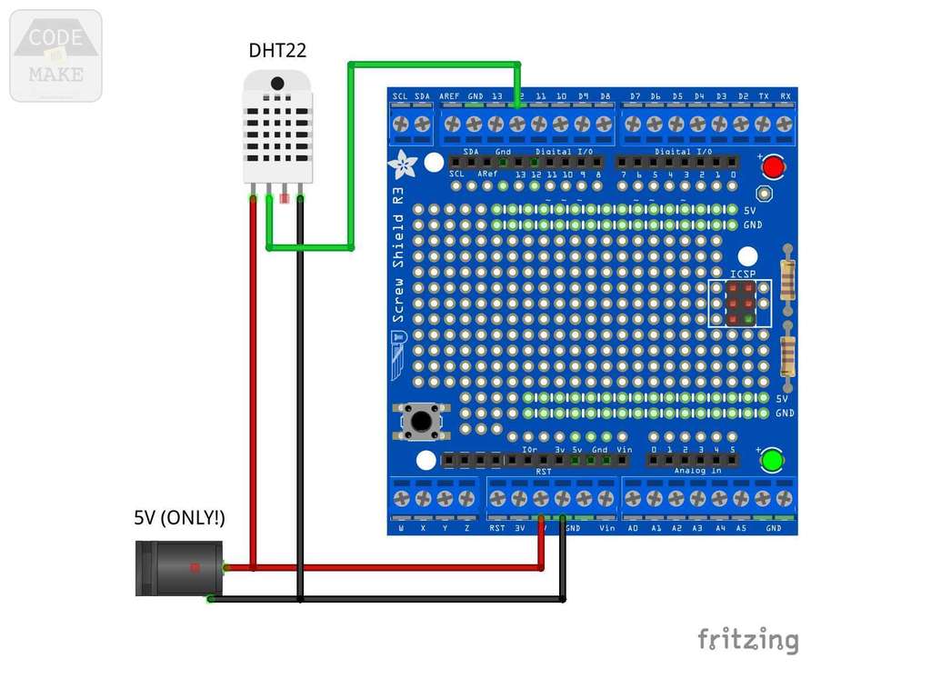 1) If you haven't already, upload the code to the Arduino...
thingiverse
Connection diagram Links to materials: Touch Buttons Arduino pro mini 5V 16MHZ Programmer Power Supply 5V 2.5A Counter MOSFET Screen Solenoid valve Encoder DC-DC step-up module Beeper Black hot melt Wires Terminal kit XH2.54 HER105 diodes Covers...
prusaprinters
Please use this diagram as a reference: If you haven't already, upload the code to the Arduino (detailed in the 'Code' section above). Insert the Adafruit Proto-Screwshield (Wingshield) into the Arduino Uno. Remove the female pin header connector...
myminifactory
Please use the wiring diagram as a reference. If you haven't already, upload the code to the Arduino (detailed in the 'Code' section above). Insert the Adafruit Proto-Screwshield (Wingshield) into the Arduino Uno. Remove the female pin header...
prusaprinters
You only need a few parts to get started as illustrated in the assembly diagram to get started with your first level. </p><p>Shaft Safety note: While shaft wedges do have their ends blunted, please use care when using...
cults3d
The layout diagram shows the view from the top: the copper strip cuts are on the underside of the board and tinned copper wire was used to make the links on the top. Materials Please note that all ebay links may fail in the future, as vendors...
prusaprinters
For the wiring please refer to the attached wiring diagram. The wires of the LED's are guided inside of the T-slot of the vertical aluminium profile and conducted through the designated opening inside of the electronics case. </p><p>A reflective...
thingiverse
Additional diagrams and photos --------------------- #### Charge amplifier for piezo-electric force transducer #### Power source --------------------- #### Full setup References ==================== * Herrel, A., Spithoven, L., van...
prusaprinters
Because I am using a 12V power supply i chose one 470 Ohm to position in series with the LEDs Step 3:Here is the electric diagram of how the LEDs and resistor are physically arranged. Step 4:Cut the wires and strip the ends to attach...
cults3d
Electronics: I’ve included a wiring diagram to wire up the Arduino Nano to the DRV8825 stepper motor driver and the driver to the stepper motor. It’s a pretty simple wiring job. Just take your time, making sure you correctly identify all the pins...
prusaprinters
(6 pieces I think)If you build it all on your desk before touching a single bolt on your printer, you will see where these parts are working together.I will post up some tinkercad screenshots as a kind of airfix model instruction exploded diagram...
prusaprinters
Check the exploded diagram for assembly orientation.Work "inner" and "outer" together for a bit then take them apart and wipe away any excess grease from anywhere it doesn't need to be.Work "outer" into "spacer" a few times then lock it down. When...
prusaprinters
A wiring diagram is included in the attached images. Step by step assembly instructions will be uploaded shortly. </p><p>GRBL configuration is dependent on the motors and drivers you've purchased. The X axis is your linear axis and the steps...
prusaprinters
For the FlipClock device two units of the PCB have been used: one to control hours and minutes flaps, and another one to control weather flaps. Block diagram Layout Subparts MSP430FR2433 MCU INA333 comparators ULN2003A drivers 3D printed...
thingiverse
There's second hardware UART that is used internally for WiFi configuration, I don't really need this feature and prefer to use second UART for GPS or OpenLager, so [here](https://imgur.com/a/DoErukI)'s how I rewired it (this is updated diagram,...
thingiverse
Images from this book including, including diagrams of the Federation class, appeared briefly in the background of Star Trek II and III, making it arguably screen-canonical! ...