hardtail motorcycle frame 3d models
132671 3d models found related to hardtail motorcycle frame.
thingiverse
Your 6 fixing holes will be in exactly the right place, first time, every time.I've since added two small stubs onto the template design so that it can also be used to gauge the correct distance away from any brackets or frames you might need to work...
prusaprinters
Here's the mod for the newer style with the U-shaped front Y idler bracket.The original design placed the belt too close to the frame which caused severe belt misalignment. This could be due to my unit being an early model, poor QC or a number of...
cults3d
Final Note: I have been using the four-piece center frame design because of printer size restrictions I had at the time, for just under three years now. The only issues I’ve run into were with the wall mount layer separation mentioned below. Besides...
pinshape
So I maximized the distance between the rim of duct outlet and the hotend heaterblock, while not colliding with the M2 frame. I included a bottom view photo to illustrate the relatively small space this all had to fit within. With this added...
thingiverse
If you want to build the clock as shown you will need the following parts in addition to the above: 2x printed STL Back-Mounting-Frame 1x printed STL ArdNano-Case 1x printed STL Stands This will fit an Arduino Nano or Pro Mini and a small DS3231...
thingiverse
*******UPDATE #2***** The bottom frame is not very rigid and the motor plate will flex when the drive is running. I have added a bearing block to support the shaft of the drive. This seems to have eliminated the flex in the bottom plate. The shaft...
thingiverse
After the frame is loosely connected, it is tightened from back to front. Start with the nut that clamps the rear package (buckle, long sleeve, rear retainer, sleeve, impeller, sleeve, washer and nut) this will give you the position of the drum. Then...
thingiverse
The photos show a frame from an IBM Selectric typewriter being bored to suit a larger mechanism, after careful concentric alignment to the existing hole. I used cutting fluid to start with but found it easier to spray a tiny squirt of WD40 on whilst...
prusaprinters
attached with a bolt on each side."spool_holder" use 30mm bolts, go though z top parts, frame, then in this part. self threading. original spool holder collides with this extruder.</p><p>"hex_key_drill_adaptor" use drill or...
thingiverse
Attach the top extrusions to the rest of the frame. 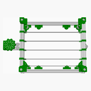 <span></span> [Top](#TOP) --- <a...
thingiverse
You will need extra T-slot nuts to mount the cases to the CR-10 frame. I do not use the SD-Card, but if you do, you will need an SD-Card extender. (There is a cut-out in the case for the display ribbon cable, which you can also use for the SD-Card...
myminifactory
In a recent video, you can see in detail how to mount a track frame (one side of the robot) here. Please let me know if you find any issues with the parts or if you would like me to create a specific block for any hardware you think could be useful....
prusaprinters
This model is in proportion to my Dilbert series. Enjoy! Print instructionsRafts: Doesn't Matter Supports: No Resolution: .2 mm Infill: 10% Notes: See notes below for helpful printing and assembly instructions Building the Model Colors (there are no...
thingiverse
I have had little success with designs that attach to the Z-axis frame and move up and down with the router. - Larger vacuum tube that works better for my dust collection. Also it pulls through larger shavings that can get caught in the...
grabcad
The transformer and load assembly is mounted on a 3/16" thick carbon steel mounting platform and the load center/distribution assembly is mounted to the standard 2" x 2" x 1/8" square carbon steel tubing frame, resulting in an extremely stable,...
thingiverse
This requires 2 of the "Latch Guide Frame" prints, 4 of the "Latch Guide Door" prints and 1 "Handle" print. All of the latch guide parts take M3*12 bolts. The rack and pinion gear setup was cut using a laser. This also includes a large diameter...
thingiverse
The motor house is big enough, and the framing and decking were designed for easy redesign and modification without the need for significant reprint. The prototype uses a remote 12V power supply (located on Level A) culled from an old PC together...
thingiverse
I've only used the holder with frameless PCB stencils, but it should also work with framed stencils by using longer M4 screws. It's essential that the stencil is at the same height as the PCB top. The rod holders determine this height, which is...
thingiverse
I found IDC box things here on Thingiverse that could be popped over the pins to make male headers into box headers and similar IDC style frames that could be put around Dupont terminals on jumpers to make matching plugs. And best of all, no 6 week...
cults3d
The curls on the head join those of the beard to frame the emperor’s rather pensive face. A laurel wreath crowns the head and separates the deeply worked curls from a flatter swirl of hair above the wreath. Technical examination has revealed that the...
thingiverse
I took the original idea, hooking the bracket onto the Da Vinci frame and made a few tweaks to improve its stability. I bolted the webcam directly onto the bracket and made sure the camera stopped drifting off-center. First, you can print the parts...
myminifactory
Please see images for further details: this 3D print file contains STLs for the following: Outer Corner Ruined Canopy Ruined Door Frame Ruined Door Wall Ruined Double Junction Ruined Inner Corner Ruined Inner Wall Ruined Rocket Ruined Rocket Girder...
myminifactory
With models like the Rebellious Slave, Michelangelo understood how light and shadow cooperate to form shape, volume, and frame. He worked primarily with the human body and believed that all beauty could be found within it. While Da Vinci thought...
thingiverse
Next step involves inserting code in order to get back home Z so enter: G28 X0 Y0; move X/Y axis to their respective minimum end stops G28 Z0 ;move z to its position where it needs be, for calibration Then you have got your leveler working perfectly...
thingiverse
Used screws, nuts and washers: Extruder: 3x M3x35mm (original) RunOut sensor: 2x M3x16mm (original) 2x M3 hammer nuts Frame mounting: 4x M5x20mm 4x hammer nuts M5 4x washer M5 Connection: 4x countersunk screw M3x14mm 4x self-locking M3 4x washer M3...
thingiverse
... ? Mod cost: depends on the 3D printed part. # Cable chain A cable chain for the i3 provides better fit and finished, and helps keep the cable straight and away from the frame at the top. ... Print one yourself; they'd add more cost to ship.
thingiverse
Trimmed 3mm from bottoms like the previous item, Used additional 4 rails for cross members under the 1000mm rails for the laser bed to sit on.)https://www.amazon.com/dp/B08Y8KCJW4?psc=1&ref_=cm_sw_r_cp_ud_ct_FAKR43V7BNB1EKJHX096boeray 2 Sets 2020...
thingiverse
Trimmed 3mm from bottoms like the previous item, Used additional 4 rails for cross members under the 1000mm rails for the laser bed to sit on.)https://www.amazon.com/dp/B08Y8KCJW4?psc=1&ref_=cm_sw_r_cp_ud_ct_FAKR43V7BNB1EKJHX096boeray 2 Sets 2020...
cults3d
A special chassis and gearbox frame is available to fit Yokomo diffs directly with the 10x15x4 mm ball bearings. It's called Option-Yokomodiffchassisbelt01 and is not relevant to normal builders. FS racing part number 511687 steel gear dif can be...
prusaprinters
I needed both types of segments, "straight" and 90-degree twist. Original design offered only the weighted base (designed for resting where placed rather than mounting to frame or enclosure). Due to limited space I wanted to attach mine to my...