armature diagram 3d models
7001 3d models found related to armature diagram.
thingiverse
I have included a wiring diagram. You won't need any soldering this time but basic electronic skills are helpful. Make sure that you know what you are doing (particularly dealing with high voltage). All at your own risk and no warranty whatsoever! is...
grabcad
For testing purposes only - sketching involved assistant In the interest of a trial, this pertains to a simple drawing - merely a sketch. assistant Exclusively for an initial attempt, the content provided is related to a rough draft - a trial...
prusaprinters
Look at the uploaded picture of the wiring diagram. This will give you an overview of how all the components need to be connected. Starting with the switch, use the close-up picture of the back of the switch to get it wired using spade connectors. It...
prusaprinters
This probably isn't for the faint of heart and I doubt anyone is crazy enough to try printing this but I still thought I'd post it because someone might be able to use parts of it (the coin slide mechanism?) or maybe at least get ideas from it. The...
thingiverse
Diagram of the bolts included. Stay tuned for more updates and more whacky weapons! I just added a video guide for assembly here DISCLAIMER: By downloading these files, you agree that I shall not be liable for any damage, injury or harm resulting...
prusaprinters
This meant that for each measurement we took we would double it and draw it on graph paper, but still only write the original measurement, because we were only blowing up the model for a diagram, not for the actual print. We used a cm ruler to keep...
cults3d
The connection diagram is in the pictures above. If the toggle switch on the power box is off then the "auto power off" system is completely inactive and your printer would work normally (no risk for auto-off). If you turn the power box toggle...
thingiverse
IF THERE ARE ANY QUESTIONS?The parameters should be self-explanatory, please see the included diagram...but to ensure your success, I'll add some suggestions here and there:For the wider end of both sockets, I usually like to add between 0.3mm and...
thingiverse
UPDATE 08Dec20: Upon multiple requests - I have just added a wiring diagram! Hope this helps.</b> <b>WIRING.</b> Upon request, here is short introduction to wiring the speaker (and remember, you can always use the enclosure as a passive speaker,...
prusaprinters
In addition, it needs “support on built plate only”.Parts required (see photo on red table):ESP8266 D1 Minired and green LEDs, two matching resistors (330 Ohm)button for manual operation (for 12mm hole)12 V DC gear motor230V / 12V DC transformerMotor...
prusaprinters
V2 dos not have a core to match the image in the top left, but instead embosses A, B, C & D inside the part.The following diagram is available in the download section too.I have a video on crimping tools and techniques that may assist: Assembly -...
prusaprinters
I used 25% infill.For a single height lampshade, the lampshade supporting ring should be put on the top lampstand section, immediately under the light fitting as shown in the diagram. For a double height lamp the lampshade supporting ring should be...
prusaprinters
Note that one 'M' (right side) and one 'O' (left side) are cut so as not to interfere with the rope indent.7 - Refer to the assembly diagrams in the pictures section as well as the uploaded pictures for putting the model together. ...The model is...
prusaprinters
For the wiring please refer to the attached wiring diagram. The wires of the LED's are guided inside of the T-slot of the vertical aluminium profile and conducted through the designated opening inside of the electronics case. A reflective screen /...
cults3d
Diagram of the bolts included. Stay tuned for more updates and more whacky weapons! I just added a video guide for assembly here DISCLAIMER: By downloading these files, you agree that I shall not be liable for any damage, injury or harm resulting...
thingiverse
Connect the wires as shown in the wiring diagram: | Arduino | Stepper Driver | Stepper Motor | | --- | --- | --- | | D11 | EN | | | D12 | DIR | | | D13 | STEP | | | 3V3 | VIO | | | 5V | VM | | | GND | GND near VM | | | | M2B | Dark Yellow | | | M2A |...
prusaprinters
This helps when connecting all the wires. Insert and glue the Tactile button from the side where a weird bevel is sticking out for the “Light Controller - Lid"Follow the wiring diagram below to plug in all the connections to the Arduino. Don't do...
prusaprinters
Refer to the included diagram for wiring to the 26 pin header; you will be connecting the thermal camera this way, and the power LED via the 470 ohm resistor. The four connectors marked Flash are for an external flash unit; there is not yet a Thing...
prusaprinters
Others might not fit to the case!)1x 5V / 4A power supply with barrel jack connectorSome 0,25mm² wires in different coloursSome 0,50mm² wires for the LED matrix power wires18x Soldering cable shoes M330x M3x8 screws21x M3 nuts (30 if you want to fix...
prusaprinters
Also multiple stages can be on the same shaft (they spin at different speeds)Also see “Freak Clock asm.3mf” under extras for a 3d model of it all put together Printing:I used manual color swaps (ie. M600) for the numbers and day of the week...
prusaprinters
(see Wiring diagram)I used headers and jumper wires for my prototype, but you might want to solder the whole thing together, if you're not planning on taking it apart later. Route the wires between the stepper motor and the walls of the...
thingiverse
The TB6600 wiring diagram I added shows a different controller and I do not know if the pinout is the same on the Octopus, so I recommend using an ohm meter and checking for continuity from the pins on the stepper socket boards to the output jacks...
prusaprinters
Because I am using a 12V power supply i chose one 470 Ohm to position in series with the LEDs Step 3:Here is the electric diagram of how the LEDs and resistor are physically arranged. Step 4:Cut the wires and strip the ends to attach...
prusaprinters
Check the exploded diagram for assembly orientation.Work "inner" and "outer" together for a bit then take them apart and wipe away any excess grease from anywhere it doesn't need to be.Work "outer" into "spacer" a few times then lock it down. When...
prusaprinters
A wiring diagram is included in the attached images. Step by step assembly instructions will be uploaded shortly. </p><p>GRBL configuration is dependent on the motors and drivers you've purchased. The X axis is your linear axis and the steps...
prusaprinters
Please use this diagram as a reference: If you haven't already, upload the code to the Arduino (detailed in the 'Code' section above). Insert the Adafruit Proto-Screwshield (Wingshield) into the Arduino Uno. Remove the female pin header connector...
thingiverse
Please use this diagram as a reference: 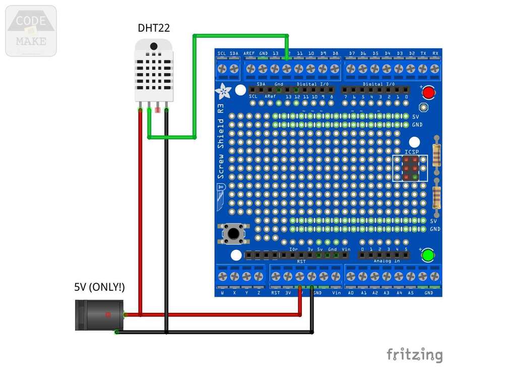 1) If you haven't already, upload the code to the Arduino...
prusaprinters
For the FlipClock device two units of the PCB have been used: one to control hours and minutes flaps, and another one to control weather flaps. Block diagram Layout Subparts MSP430FR2433 MCU INA333 comparators ULN2003A drivers 3D printed...
prusaprinters
Place the corner, screw, put the arms, screw, … · There is a hole for each screw, you can’t get it wrong. · For the wiring, please refer to the diagram. Firmware At this point all you need to complete the hardware part is to upload the firmware to...
cults3d
The layout diagram shows the view from the top: the copper strip cuts are on the underside of the board and tinned copper wire was used to make the links on the top. Materials Please note that all ebay links may fail in the future, as vendors...